

As designers sometimes don’t work with commercial considerations in mind, it is often a valuable experience for students when design colleges provide practical experience to help them understand the compromises and challenges of commercialising ideas.
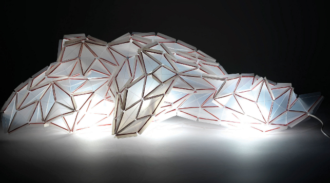
Shine on you crazy diamond: Alice Gruhle’s innovative lamp concept made of diamond-shaped modules
HfG Offenbach University of Art and Design in Germany succeeded in doing just that by giving its students an assignment to design a utility item that would meet all the requirements of series production.
Initially, the students were only able to use scissors, paper and glue to create conceptual models of their ideas. However, as the project developed, one successful student would have access to the very latest injection moulding technology to produce a working model of their design.
At the invitation of project supervisor, Professor Frank Zebner, the seminar event was supported by master toolmaker Jörg Müller, who is also the technical sales manager in Germany for Protomold, the specialist injection-moulding service from Proto Labs.
Jörg was on hand throughout the project to advise students on ways to apply the rapid injection moulding process to their design process.
The seminar concluded with Professor Zebner and Mr Müller selecting the best design for a short production run to be made using polypropylene: the winning designer was Alice Gruhle who had designed a lamp concept made of diamond-shaped modules.
Enter the fold
The seminar began with an investigation into different folding techniques. The objective was to construct as many different shapes as possible using both sober symmetrical grids and playful forms resembling those made by origami artists.
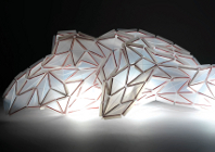
Alice Gruhle and her Polymorph lamp
The participants were then encouraged to draw on this collection of shapes to come up with their unique product design.
Initially, Alice Gruhle experimented with a grid of squares, each divided into four triangles of equal size. She then transferred the grid onto a thin sheet of polypropylene, cut out the triangles and then joined them back together in their original arrangement with tape so they could be folded along the dividing lines.
It was at this point in the project that Alice benefited from the knowledge and experience of Mr Müller as he pointed out that it would not be technically possible to make a single working part with so many folding hinges using the injection moulding process. He explained that from his experience, the plastic would cool down before it could completely fill out the tool.
With this in mind, Alice kept on experimenting by stretching the squares into diamonds. To join these diamonds together she then added wings that could flap back and attach to the long-sided wings of the neighbouring module.
Clipped wings
With her paper prototype she used simple paper clips to join the wings but when it came to the modules cut from sheets of polypropylene, she chose ordinary rubber bands to make the connections.
Alice explained: “You can produce more complicated structures using diamond-shaped modules than you can with comparatively rigid squares. It is possible to, not only construct regular and closed bodies from them, but also open and chaotic structures. This really appealed to me!”
Bright ideas
For the university’s end-of-term show, Alice produced 500 modules and joined them to create a single sculpture. “I spent an entire night working on it,” she recollects.
A low-energy bulb protruded up from a base and glowed inside the body of the lamp. This made the lamp stand out from its surroundings and the effect was particularly impressive in the dark as the light seeped through the hinges where the translucent material was thinner.
Then, by using ProtoQuote and ProtoFlow analysis, Alice worked on her design so that the module would be optimised for rapid injection moulding production.
She has since received her first delivery of injection moulded modules and is very pleased with the outcome. “It’s really like Lego,” she says.
“Every part must be right so that they all fit together perfectly.”
In comparison to the early modules, milled using the university’s own facilities, the injection moulded versions are stronger as the process allowed them to be 0.6mm thicker. The notches on the tips of the diamonds are square, rather than round, and the folding hinges could be bent in both directions – not just in one as was the case with the prototype.
It was at this stage that Alice also changed the rubber band concept for connecting the diamonds together; finding that when they wrapped two or three times around the wings they became brittle. She replaced these with perfectly fitting silicon rings.
Alice has called her design ‘Polymorph’ and has since used some 150 injection moulded modules to create a cocoon-like hanging lamp. Her design has subsequently been featured in German design magazines and was showcased at Euromold last December.
www.protolabs.co.uk
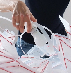
Alice Gruhle glows with inspiration when building her ‘Polymorph’ lamp


_LB.jpg)