Before we make a start we need to be aware of the two broad classes of structures that will greet us when we embark on our Finite Element Analysis (FEA) simulations.
If we ignore mechanisms then we can say that the two groups are “determinate” and “indeterminate” structures. Sounds very complicated but we can easily understand these terms as follows: if there is a single (unique) load path within the component then we call this a “determinate” structure.
We can literally determine where and how any applied load will go to ground. A simple cantilever therefore is a determinate structure because all loads must pass through the cross-section of the beam (to ground at the supported end).
The simple cantilever can be changed to an indeterminate structure by adding a prop to the tip of the beam. Now some of the load travels through the prop and some through the cross-section of the beam.
In the modified structure there are now multiple load paths available and the structure has a degree of redundancy (cutting, or putting a hinge into, one load path will NOT lead to collapse).
How can we deduce how much load travels through the prop and how much through the beam? As long as we apply the load SLOWLY then the internal forces will be apportioned on a relative stiffness basis.
If the prop is much stiffer than the beam then the bulk of the load will go through the prop. The reverse is true if the beam is relatively stiff. It’s common sense really.
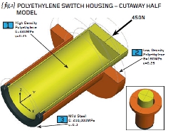
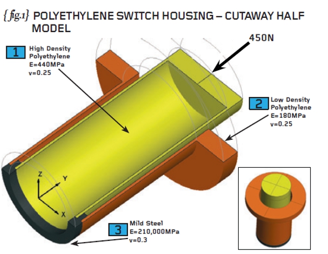
In order to describe how FEA works, we need an engineering example. { fig.1} shows a circular plastic switch housing comprising an inner sleeve (high density polyethylene), an outer sleeve (low density polyethylene) and a steel collar.
We need to assume that the plastic sleeves are bonded properly to the steel and that the joint interfaces can carry the applied load (450N). { fig.2} shows the switch housing in cross section with key dimensions (in millimetres) added. The inside and outside diameters of the two plastic sleeves are given as well as the effective length of each of the sleeves.
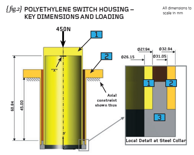
The purpose of the switch housing (are you sitting comfortably for this?) is to provide a failsafe mechanism for the emergency load of 450N. At this level of load, the axial movement of the casing (at “X”) has been designed to be 2mm and therefore sufficient to activate a micro-switch fitted inside the housing. Now, if you believe that, you’ll believe anything!
The underlying principle of FEA is that of a stiffnessbased solution (we will have to revisit this at a later date but the bulk of the FEA carried out uses this notion of stiffness). We need therefore to build up a reliable estimate of how stiff our particular component is.
Stiffness is a blanket term for axial stiffness, bending stiffness, shear stiffness and the like so you can appreciate that the notion of “stiffness” for a complicated component is quite a complex idea. What the FEA method does is to break the real structure down into a finite number of chunks or “elements”. These elements (talking in 3D now) have simple shapes such as bricks and wedges and the mathematics for calculating the stiffness of these chunks is relatively straightforward.
Once we have been able to calculate the stiffness of the individual elements, and perfected the correct way to join them together, then we should be able to represent the complex stiffness of the real part.
If we know the stiffness of our component then we know how the loads will “hunt” for the right load path and we can solve determinate and indeterminate problems. For once we can solve real problems without gross simplification.
So what do we really mean when we use the term “stiffness”? The term stiffness links the forces applied to a structure with the resulting displacement of the structure. A bicycle can be very stiff for example – a heavy load on the pedals creates a small amount of flex.
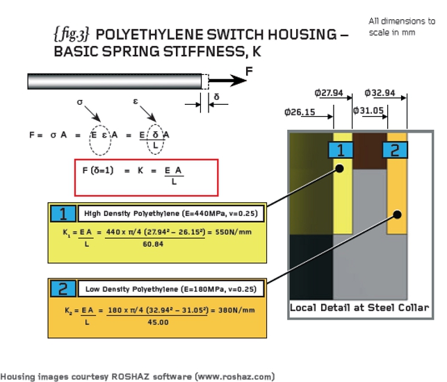
The stiffness of something is best regarded as a special kind of force – it is the force required to give a unit displacement (and has the units of N/mm for example). { fig.3} shows a bar loaded by a force, F, such that a displacement, ä,is induced at the end. If you follow the working in { fig.3} you will see that the stiffness of that bar is given by the expression “EA/L” and has the units of N/mm as promised.
The first step in solving our switch housing problem is to calculate the basic spring stiffness values of the two plastic sleeves noting that we use the effective lengths of each. Check my working (because it’s Christmas eve as I write this) and we will continue next time…
R P Johnson BSc MSc NRA MIMechE CEng 
Part ten of an engineering masterclass: Basic Principles of FEA