In the previous article we started to think about the Finite Element Analysis (FEA) of a simple linkage.
The main objective was to apply realistic constraints that do enough to stop movement of the linkage as a rigid body but no more. A large number of FEA models are over-constrained and here we seek to apply realistic constraints consistent with the real structure.
The homework from the previous article was to assess whether the proposed loading was sensible and, if it was, then to show the linkage as a free-body floating in space.
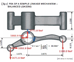
{ fig.1} demonstrates my solution. I have shown all the forces acting on the linkage as imposed by the three closefitting pins. Take time to check that the load values quoted render the linkage in force equilibrium (in the X, Y and Z directions) and moment equilibrium (in the X, Y and Z directions).
The static FEA will now take these loads and apply them as a pressure distribution to each of the three bores. If you are concerned about the actual stress variation in the immediate vicinity of the bores then you will need to carry out a detailed contact analysis with the pins included in your model.
The method shown here will generally give you a worst-case stressing scenario because we will allow the linkage to deform as freely as possible.
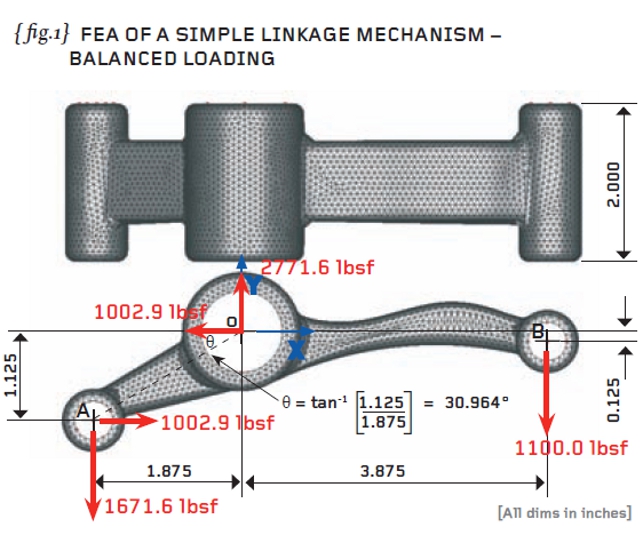
{fig.2} shows the load resultants applied at each of the three bores. The pressure magnitude vectors (nodal forces in fact) are added to the figure and these vary over a 180-degree sector according to the work done by Gencoz and colleagues.
If you don’t have the Gencoz empirical distribution then a constant pressure distribution will suffice making sure that the 180-degree loading patches are orientated properly to give you the load directions you require.
It is important to ensure that the pressure loading applied to your model induces the correct thrusts and that these, acting together, give force and moment equilibrium. The load balance achieved using the ROSHAZ software is excellent and a table of load resultants (about the origin) has been added to { fig.2}.
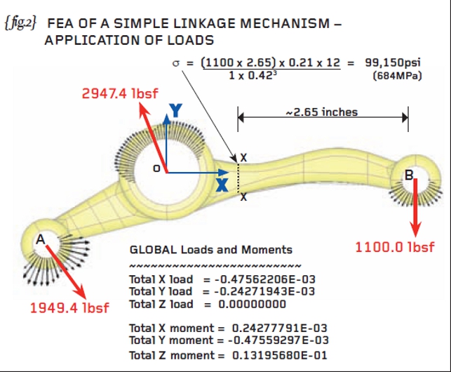
Having checked that the load balance is acceptable we can now proceed with the application of the 3-2-1 minimum constraint. I have applied these to one of the end faces of the central boss and we will examine these in detail later on.
Material properties were applied consistent with the elastic properties of Aluminium that is: Young’s Modulus (E) = 10.15E6 psi and Poisson’s Ratio (V) = 0.3. Our chosen system of units was pounds-force and inches.
{ fig.2} shows an approximate hand calculation for the bending stress at section X-X (located 2.65 inches from the centre of bore B). The bending stress is given by My/I where M is the bending Moment (1100 x 2.65 poundsforce-inches), y is the half-height of the section (0.21 inches) and I is the Second Moment of Area of the section X-X (bd3/12 or in this case 1 x 0.423 /12). The resulting bending stress was calculated as 99,150psi or 684MPa in SI units.
{ fig.3} shows stress contours of the first Principal P1 stress with the 3-2-1 minimum constraints also shown on the end face of the central bore. Note that there are no telltale high stresses at the 3-2-1 supports – further evidence that the load balance was good. A check of the reactions at these constrained nodes should also be carried out.
The maximum P1 stress of 251,567psi (1735MPa) occurred on the tight blend between the long arm and the outside diameter of the main boss. A larger area of high stress occurred on the concave side of the long arm (near the central boss) and here the peak P1 stress was lower at 124,206psi (857MPa). The hand calculations at section X-X are largely consistent with the stress predicted by the FEA (hand calculation was 99,150psi compared to the FEA at 124,206psi).
Thus we have completed the FEA of a simple linkage under balanced loading and minimal constraint. We can be confident that we are not over-constraining the model and next time, in the final installment, I will re-run the linkage with some of the wrong ways to address this problem!
Part fifteen of an engineering masterclass: realistic constraints
Default