Pump action

15 January 2009

Process types: Manufacture and Simulate

Digital shape sampling and processing (DSSP), CAD and rapid prototyping technologies combine to enable the digital reconstruction and manufacture of a replacement for a damaged pump impeller in record time. By Bob Cramblitt.

In America, Thanksgiving is a time to take stock of one’s good fortune, usually pertaining to health, home and family. John Allen, maintenance superintendent for Owensboro Municipal Utilities in Kentucky, had additional thanks to give over the holiday: a centrifugal pump vital to the capacity of his electrical plant was back in service, much faster than originally anticipated.

A couple of weeks before Thanksgiving, the pump, used to generate hydraulic pressure to start a steam turbine in the Owensboro power plant, had a major malfunction. Half of the shroud was destroyed and the tops of the impeller blades were sheared.

Geomagic

ADC used Pro/Engineer to pattern the master vane, making exact copies around the impeller’s axis (Courtesy of ADC) built from Geomagic Studio's polygon model

Without the pump, the generation unit couldn’t operate, reducing the power plant’s capacity by a third. Owensboro supplies electricity to 26,000 customers and water to 24,000. There was no backup for the pump, since under normal conditions it will perform for 40 or 50 years without needing replacement. Nor were there CAD models or documentation to help rebuild it.

Under pressure to replace the pump quickly, Allen turned to long-time Wisconsin, USA-based contractor Rotating Equipment Repair (RER). RER has nearly 25 years of experience and a 38,000-square-foot facility housing the latest in pump repair and manufacturing equipment. The company also has nearby partners with unique credentials: Advanced Design Concepts (ADC), a company that specialises in the use of digital shape sampling and processing (DSSP) to digitally reconstruct parts for companies such as Harley-Davidson, Briggs & Stratton, and Simons-Voss; and Signicast, which operates one of the largest, most innovative foundries of its kind in North America.

Traversing physical and digital worlds

The pump project began on the evening of November 8, when RER received the severely damaged pump from the Owensboro plant. The next day, RER disassembled the pump and began preparing it for reconstruction.

Based on the original dimensions of the pump, the damaged remains of the impeller, and its experience in pump design, RER created a 2D CAD model of the impeller in AutoCAD and obtained cross dimensions from it. Over the weekend, a pattern maker at RER built up an impeller vane in clay to match the specifications of the original.

ADC received the clay impeller and the AutoCAD dimensional drawings on Monday morning, November 13. The company was a natural fit for this project. ADC is less than seven miles from RER, but more importantly, the company has used DSSP technology to recreate everything from classic Harley-Davidson fuel tanks to cylinder head ports for Nextel Cup race cars.

DSSP enables companies to navigate easily between physical and digital worlds. This capability helps companies speed development of products based on legacy designs, conduct accurate engineering analysis with digital models that replicate manufactured parts, inspect faster and more precisely, and continuously improve products over their lifespan.

Accelerating the Design

ADC’s task was to create a 3D digital model of the impeller vane as the basis of a 3D CAD model for use in the manufacture of the replacement. Since the impeller vanes were identical, ADC only needed to capture the shape of one vane, then recreate it for the CAD model. By noon, the impeller had been scanned and its geometry captured in the form of a point cloud using a Cimcore scanning head with a Romer arm.

We didn’t have a spare part, so it was important to replace the pump as quickly as possible

John Allen, Owensboro Municipal Utilities in Kentucky

The point cloud was read into Geomagic Studio DSSP software which was used to automatically align the scan data, then “wrap” the point cloud with a polygon model. The Wrap module of Geomagic Studio eliminates time-consuming and labour-intensive surface reconstruction work by mathematically wrapping a polygonal surface around point cloud data. The patented process is automatic, but gives users control to fine-tune the model if necessary. Wrap creates watertight polygonal models without approximation. The polygon model was saved as an STL file that could be used as a guide for the CAD model.

“Geomagic Studio enabled us to align the scan data easily and to quickly create an STL model that accurately depicted the part in a form that Pro/Engineer CAD/CAM software could handle,” says Chris Mulhall, the ADC design engineer who managed the project. “This allowed me to model the part and simultaneously compare the model to the scan data in a time-efficient manner.”

The Geomagic model served as the basis for building a parametric model of the impeller in Pro/Engineer. Mulhall overlayed the scan data onto the Pro/E model of the master vane as it was being created to ensure accuracy. Exact copies of the master vane were then made and patterned around the impeller’s axis. Geometry from the shroud on the bottom of the impeller was used to recreate a model of the top shroud.

The initial plan was to produce a two-part model, which would then be machined, assembled and welded. But, some quick adjustments by RER led to a much more time-efficient solution.

Casting the quick way

RER had originally planned to do a sand casting mould of the impeller. This requires intricate wooden moulding boxes that are hand-made and filled with casting sand or a mixture of sand and clay. The process is labour intensive and the resulting metal castings are rough, characterised by a sand-like texture on the mould. Sand-cast moulds usually require a fair amount of hand work – including hammering, grinding and sanding – to make them suitable for manufacturing. They also take a lot of time, a luxury RER didn’t have.

Geomagic

A close-up of the damage sustained by the impeller (Courtesy of RER)

“It can take four to six weeks to get foundry time for a sand casting, then another two to three weeks for the foundry to complete the mould,” says Eric Kirschling, the RER mechanical engineer who headed up the impeller project. “The standard turnaround time is eight-to-twelve weeks, which we couldn’t afford.”

To shorten the turnaround time and increase accuracy of the mould, Kirschling looked into investment casting. In this process, a wax mould is coated in ceramic and placed in a furnace, where the ceramic hardens, and the wax melts away, leaving a finished ceramic mould. RER found a way to further accelerate the process by working with Signicast in nearby Hartford, Wisconsin.

Signicast creates the casting using a rapid prototyping system that produces the mould directly from the CAD model. A hard coating is applied to the rapid prototyped mould and liquid metal is poured into it to form the cast part.

“The end product is better quality than a sand casting,” says Kirschling; “it’s smoother and has tighter tolerances.”

But Mulhall had finished the two-part CAD model of the impeller when Kirschling contacted him with the change in plans, which now required a one-piece model.

“It took Chris about an hour to switch gears and create the one-piece model in Geomagic Studio,” says Kirschling.

The entire digital reconstruction – from scanning to geometry processing to 3D CAD model – took just a day and a half. On November 14, RER had the solid model from ADC, ready for Signicast’s process, sometimes called quick casting.

A reason to give thanks

Signicast did the rapid prototyping and created three investment castings in a week. RER heat-treated the castings that night, then machined and balanced them the next day, November 22. The pump was fully assembled and shipped by the end of the following day, which happened to be Thanksgiving.

The combination of DSSP, CAD and quick casting saved anywhere from six to ten weeks of time by Kirschling’s estimations.

At Owensboro, John Allen and his team had also been making best use of their time. Although the pump replacement was only part of his problem, it was a major part, as an entire energy-generating unit was out of service until it could be replaced. While work was being done on the pump, Allen and his team were busy cleaning the tank in which the pump was submerged and repairing damage in lube oil piping caused by the parts of the pump that blew into pieces.

“We didn’t have a spare part, so it was important to replace the pump as quickly as possible,” says Allen. “RER met our needs to get the pump back and working as soon as possible, and now we have a couple of replacements if ever needed.”

www.geomagic.com

Comments on this article:

Street machine

09 January 2009

Process types: Design, Prototype and Visualise

Frances Corbet talks to Bombardier Recreational Products, about how the Canadian company is strengthening its creative output and pushing forward its breakthrough powersports craft for land, sea and snow

For Bombardier Recreational Products (BRP) the adventure began more than 60 years ago with the creation and commercialisation of the first snowmobile.

Today, whether it is on snow, on water, on trails or on the open road, this Canadian company with its headquarters in Valcourt, Quebec, promises to ‘move’ people both physically and emotionally with its motorised recreational vehicles.

“Design is about seduction,” says Denys Lapointe, executive vice-president of Design and Innovation at BRP. “From a design standpoint, BRP pushes craftsmanship to new limits, giving the utmost attention to detail so that customers can enjoy every thrilling second on one of our products.”

The company claims that innovation is part of its DNA. In the 1960s the head of design Anselme Lapointe and his team were pioneers in the powersports world, launching, amongst other products, the very first Sea-Doo personal watercraft. Following in his father’s footsteps, Denys Lapointe is committed to keeping innovation at the very core of the company’s growth. “Our design philosophy is to create highly innovative, functional and exciting motorised products to exceed people’s recreational needs,” he explains. “We are always looking at challenging current paradigms to create the new paradigm.”

On the road

One of its most recent paradigm-shifting products is the Can-Am Spyder roadster, which rolled off the assembly line in Valcourt in September 2007, and marked BRP’s first foray into the on-road vehicle segment. With its unique Y-architecture, having two wheels on the front and one at the rear, the vehicle is described as being part motorcycle, part sports car. Its features include the Vehicle Stability System, engineered in conjunction with Bosch, which includes anti-lock brakes, traction control and stability control systems. It is powered by a Rotax 990cc V-Twin engine, which was designed and manufactured at BRP’s Austrian manufacturing facility.

Having only been on the market a year the Can-Am Spyder is not only catching the eye of consumers but has also caught the attention of Hollywood producer Michael Bay who has confirmed that the roadster will appear in his upcoming film ‘Transformers 2: Revenge of the Fallen’ (due for release in June 2009). In fact, this isn’t the first time BRP products have been featured in a Hollywood film as the Ski-Doo MX Z REV platform snowmobile ‘starred’ in the 2002 James Bond film ‘Die Another Day’.

A hotbed for design

In order to keep introducing innovative products and remain the leader in its traditional markets as well as gaining market share in others, BRP has made some substantial investments in recent years. In 2006 the Advanced Technology Centre (CTA) was opened in Quebec as a centre for research and innovation focusing on the development of new leading-edge technologies.

September 2007 saw the launch of the Regional Innovation Centre in Gunskircghen, Austria, which was built to provide BRP Rotax with a stimulating setting for the development of new engine technologies. In September 2008 a 5,000m2 Design and Innovation Centre was unveiled at the company’s corporate headquarters in Valcourt. The plan to build the Centre Design and Innovation Laurent Beaudoin, named after the company chairman who has had a major role to play in its success over the past 45 years, was revealed in 2007 and is the result of a $15 million dollar investment.

“Innovation has been over the years a key contributor to the growth and success of BRP,” says Lapointe. “We believe that consolidating all design activities into one inspiring centre can only strengthen our creative output and therefore increase our success in the future.”

All stages of the design process from creative thinking to prototyping will take place within the new Design and Innovation Centre. “BRP decided to concentrate in the same facility a large portion of its creative force, a team of 60 individuals ranging from industrial designers, graphic designers, engineers, human factors experts, mechanics, CAD technicians and modellers,” says Lapointe. The building is structured in five sections: the central hall with administrative functions and meeting rooms; two open offices overlooking the very long main studio floor with its adjacent succession of clay rooms; and the basement contains all the shops required to build functional prototypes. “This working environment increases the capacity to allocate temporarily more people to a project and get more creative output and synergy between each design team,” adds Lapointe.

As Lapointe argues, the centre allows for greater interaction between designers and others involved in the design and development process. “The main goal is to bring everybody together to increase the creative output, which ultimately translates into better products that respond to the consumer even better than before,” he says. “So, creating the right environment that fosters creativity is one of the main goals.”

BRP designers never work in isolation purely concentrating on just their specific area. “Being all together will allow the various members of the design and innovation team to use their creative talent to ‘pitch’ or work on more themes than before,” says Lapointe. “In other words, it will be possible for a watercraft designer to propose a concept for the next generation of snowmobile and vice versa. In fact, that’s exactly what we did when we designed the Can-Am Spyder roadster. And we didn’t just invent a vehicle, we created a market.”

Design exploration

The design team use both hard and soft process tools (such as brainstorming techniques) to discover and explore new product opportunities. “They’re also constantly developing new creative approaches to improve the innovation process,” comments Lapointe. The team do not necessarily always carry out consumer research at the start of the design process. “At the beginning, we do unconventional focus groups with consumer observation sessions sometimes with lead user type of individuals when applicable, otherwise we carry out our concept development based on our own hypotheses and validate these hypotheses later with targeted consumers and sufficiently evolved prototypes,” says Lapointe.

However, when it comes to actually converting ideas and concepts into market ready products, Lapointe doesn’t give too much away on the processes used. “The design process is an integral part of the global BRP new product development (NPD) stage gate process, similar to other stage gate processes that exist elsewhere in other industries, but we also have our own proprietary innovation process that feeds into our typical NPD process. Unfortunately we chose not to reveal too much on the matter but it helps us identify potential new paradigms.”

In order to connect with the consumer, BRP has established an approach that it argues is based on a perfect balance of three key fields of expertise - design, engineering and marketing. So, just as designers don’t work in isolation from one another, they do not operate in isolation from engineers or marketers either. “Several designers, engineers and marketers are involved in our NPD process, where we function based on what we call our triad methodology, where the prime focus of everyone is to find the perfect balance amongst all ingredients that will satisfy and delight the end user,” says Lapointe. “With the triad’s complementarily yet diverging point of views, this brings up very interesting debates, but at the end of the day, we usually obtain the wow factor that makes consumers come back to BRP.”

The role of technology

In the design studio a number of design tools are used including Catia and Rhinoceros 3D for CAD with sketches realised using Adobe Photoshop and Corel Painter. They also use portable 3D scanners - Handyscann - from Creaform to digitalise clay models.

“The main benefits of using the 3D scanner are increased precision and time saving,” says Lapointe. BRP designers use the laser scanner to acquire the x, y, z coordinates of millions of points on a clay model of a watercraft or snowmobile, for instance, and directly generate a polygonal mesh, which is then converted to Class A surfaces.

Over the years, the introduction of such new technologies has obviously had an impact as to how products are developed. “Although the creative process is very similar to what it was, the development process has changed drastically over time and we are very fortunate to have these latest tools to design and develop our products since they are getting more sophisticated and the consumers constantly expect more from us,” says Lapointe.

Global reach

Although all design and innovation is located in Valcourt, some research and development as well as manufacturing takes place at various sites around the world. “The Ski-Doo snowmobile, Sea-Doo personal watercraft and Can-Am Spyder roadster are manufactured in Valcourt,” says Lapointe. “Lynx snowmobiles and our utility Ski-Doo models are manufactured in Rovaniemi, Finland. We manufacture Sea-Doo sports boats in Benton and Evinrude engines in Sturtevant, both in the USA. Our Can-Am all-terrain vehicles are made in Juarez, Mexico and we have a plant in Guangdong, China for our lower hp Evinrude outboards.” So, overall its manufacturing presence spans six countries, its marketing reach extends to over 80 countries and it has over 5,000 dealers and distributors around the globe.

However, as Lapointe argues, you can have all the facilities and tools available to bring products to market but it’s really the people that create. “Ultimately, the creative output is only as good as those who feed it,” he says. With its new design and innovation centre the company is looking to attract even more talented designers. “We are looking far ahead. We need people who are also looking far ahead and who want to share their talents. The Design and Innovation Centre Laurent Beaudoin is sending out a clear message: if you want to have a career in design; if you want to do it in the powersports field; if you want to do it with the best resources and in the best environment in the industry… start looking to Valcourt and contact us.”

www.brp.com

A brief history of Bombadier recreational products

Joseph-Armand Bombardier was a mechanic who dreamt of building a vehicle that could ‘float on snow’. In 1937 he designed and produced his first snowmobile in his small repair shop in Valcourt, Quebec and in 1942 he set up I’Auto-Neige Bombardier Limitee in order to build these tracked multi-passenger snow vehicles. However, with the onset of the Second World War he switched gears and developed vehicles for the military. When the war was over, he diversified his business yet again first by producing tracked snowploughs and then by making all-terrain utility vehicles for the forestry, mining and utilities industries. However, Bombardier still dreamt of developing a fast, lightweight snowmobile that could carry one or two people and in 1957, with the development of smaller and more efficient engines, he resumed his efforts to build a ‘miniature’ snowmobile. He worked alongside his eldest son Germain and together they developed several prototypes of a lightweight snowmobile and finally, in 1959, the first Bombardier snowmobile went on sale. Interestingly, the Ski-Doo was originally intended to be named the ‘Ski-Dog’ because Bombardier meant it to be a practical vehicle to replace the dogsled for hunters and trappers. However, a painter accidentally misinterpreted the name and painted Ski-Doo on the first prototype.

Along with snowmobiles, the 1960s saw the launch of the first Sea-Doo personal watercraft. Joseph passed away in 1964 and left the company in the capable hands of his sons and sons-in-law who reorganised and decentralised the company and also changed its name to Bombardier Limited. During the 1970s, the company created further motorised recreational vehicles including the Can-Am brand of off-road competition motorcycles. The 1970s and 1980s also saw the company diversify into railway and aeronautical products and become a multinational corporation known as Bombardier Inc.
On 27 August 2003 Bombardier Inc announced the sale of its Recreational Products division to a group of investors, including the Bombardier family, forming Bombardier Recreational Products (BRP). Today, as a privately held company, BRP is a world leader in the design, development, manufacturing, distribution and marketing of motorised recreational vehicles.

Comments on this article:

Ice, ice, baby

09 January 2009

Process types: Design and Prototype

Inspired by the mere glimpse of snow over the Christmas break, Stephen Holmes dons his woolly hat and gloves to investigate the world of winter sports

Strapped in

Gliding down powder-covered slopes gives a feeling of freedom like no other, but ironically requires that the rider is strapped tight to the board via cutting edge bindings technology.

Option snowboards are based in Vancouver, Canada, and have been producing boards and bindings since 1992, winning awards and X-Game gold medals ever since. Their 2009-10 bindings incorporate lightweight design, comfortable fit along with technology like the base plate shaped to allow for a natural board flex underfoot.

Option Snowboards engineering and design manager Jason Kennett explains that the designers produced hand sketches, before his team proceeded to 2D AutoCAD and 3D modelling in SolidWorks.

“Our production factory in Asia uses Pro/Engineer, so they basically re-modelled the binding in that program to produce tooling,” he says. “A few SLA prototypes were made to confirm some details, and then prototypes were produced with production materials to validate weight and mechanical properties. Finally production tooling was produced.

“Trying to maintain the look and feel of the designer’s concepts through two separate modelling processes was a pain in the ass,” concludes Jason, having admitted that in the short timescale to get the bindings into production they had already designed them before selecting the production facility.

The end product is a quickly adjustable piece of kit with a high back to aid forward lean and the high back attachment outboard of the heel cup to allow for a better fit inside the boot, amongst a litany of other features to give you control when you get onto the slopes.

www.optionsnowboards.com

Gripping stuff

Activities require the right equipment. Sunday afternoons at home require a hot cup of tea, a selection of biscuits, and most importantly the Antiques Roadshow. But when you’re gripping on for grim life through howling winds and freezing temperatures, to an ice-face that could collapse at any second, you’re going to need something a tad more secure.

Black Diamond is a tried and trusted name when it comes to ice climbing, with the company’s designs taking into account not just the conditions facing the axes, but also the person clinging to them.

“The big concept was to seamlessly blend form and function,” says Black Diamond designer Paul Terry. “They had to be sexy and perform flawlessly.”

The Cobra’s inspiration is its namesake, the shaft echoes the hood of the snake, and the grip the belly scales, maintaining function through an incredibly stiff upper shaft, while the directional grip is comfortable and, like the Viper, is designed to be less fatiguing when hanging.

For the design process, an engineering ‘mule’ with all the critical geometry is created in Unigraphics NX. Then hand sketches and digital sketches are made in Alias Studio and Photoshop before being modelled and surfaced in Alias Studio. NX Nastran is used extensively throughout for strength testing.

“These designs wouldn’t have been possible without the digital tools we used,” explains Paul. “The information available at every step is a key part of truly removing the line between form and function.”
www.bdel.com

Its all downhill from here

For those of us whose only view of snow will be the grey slush clogging the gutters as we sit blocked in traffic, there’s hope that we can still experience the weaving, adrenaline peaking experience of snowboarding thanks to the 360 from Franz Sommacal.

“The concept was to create a new action and extreme sport like snowboarding, surfing or skateboarding,” says Franz. “I wanted to invent a summer snowboard with the possibility to use it over different surfaces.”

The wheels are connected using a flexible shaft, with the rider placing their feet into the inner part of the wheels, resulting in a sensation closer to snowboarding.

The product of four months of constant R&D, the original idea is a product of ‘off piste’ activities. “I remember that I was playing with an orbital wheel from a skateboard on the table between the beer glasses… The form was a natural consequence of the materials, mathematics and physics of the object.”

Built up using Alias, SolidWorks and using Maxwell Render for light simulation, Franz admits that the product will need to take advantage of strength testing software if it ever finds a funding partner to help make this ‘winter sport’ a reality for those not so blessed with snow.

www.zerofra.com

Comments on this article:

Material gains

09 January 2009

Process types: Collaborate and Manufacture

Cambashi, the leading business and marketing consultancy, reviews a bright spot in today’s gloomy environment. Martin Smith and Nick Ballard spoke to key machine tool and software suppliers, industry experts and academics to discover the state of play in the composites market

Military aircraft programs have been the proving ground for carbon composite materials. Usage has now crossed over into commercial aircraft, and other areas, where these materials offer significant benefits over their metal counterparts. Corrosion and fatigue of aluminium airframes and surfaces, for example, makes maintaining these aircraft increasingly expensive. Composite structures, on the other hand, remain chemically inert, whilst being stronger and lighter than metal.

The Boeing 787 Dreamliner will have 50% of composite materials by weight, compared to just 10% in the Boeing 777; and the Airbus A350 XWB will have 52% by weight, compared to 23% in the A380.

So what are these new materials and techniques? In general composites consist of a fibre structure inside a matrix of resin, where the resin protects the structure and holds it in place; loads are transferred to the fibre structure which acts as a reinforcement. Glass is still probably the most-used fibre, but increasingly graphite (carbon) and aramid, known by the trade-name Kevlar or Twaron, are used. Resins typically comprise two types: thermosets (which cure permanently when heated) and thermoplastics (which soften when re-heated).

Exactly half of Boeing’s 787 Dreamliner is made out of composites materials. Images courtesy of the Boeing Company

Material is laid-up on a tool or mould to form the composite part using various processes. There are four main composite manufacturing processes: Laminate Ply, Tape Laying, Fibre Placement and Resin-Transfer Moulding. The part produced is then cured or hardened in an autoclave or industrial oven; some parts require placing in a vacuum bag inside the autoclave to ensure proper resin transfer across the whole part. The main difference between these processes and traditional production methods is that they add, rather than take away, material. Currently, much of the lay-up process is undertaken by hand and processes like Resin-Transfer Moulding and Laminate Ply are still labour-intensive.

Uptake of composites in automotive is increasing, but it will be at least five to ten years before they are more widely used in production models

The software challenge

This produces new challenges for software suppliers who supply design and manufacture systems for composites. The major vendors, such as Siemens PLM Software and Dassault Systèmes rely on close cooperation with Airbus and Boeing to develop design solutions, often in association with small developers close to the production facilities. Vistagy, a Waltham, MA-based company, is a recognised leader in Composite Design environments, which integrate with all the leading CAD/PLM systems. MATERIAL, a Belgian developer, is a leader in Filament Winding software with CADWIND. Tooling, such as wing panels and fuselage sections, upon which material is laid-up, is similar to that used in conventional mould and die and flat-pattern development. Manufacturing software suppliers like Siemens PLM Software, Delcam and JetCAM are already developing their business in this area. Specialised cutting, drilling, fixtures and tooling are still required to suit the particular type of composite being prepared.

Driving Composites machines

Many of the machine-tool suppliers provide their own programming solutions to drive composite machines; these can be very large (tens of metres long and wide) and operate on up to 7-axes, to apply material at the correct angle and thickness. There are three main types of machine for material placement: Automated Tape Laying (ATL), Automated Fibre Placement (AFP) and Filament winding (see box out). Other machines are used for cutting and preparing the material for lay-up and for trimming and drilling the finished part.

NC machines for material placement

Automated Tape Laying (ATL) - A numerically-controlled (NC) machine which is mainly used for flat, or near-flat, parts with uniform, or near-uniform, thickness. This limits the class of parts produced, but is quick and cost-effective (compared to manual methods). Tape, with unidirectional fibres, rather than the bi-directional fibres of woven tape, is usually pre-impregnated with resin and applied wet, though in some cases, dry-fibre, without the resin, is used. The tape is applied by a delivery head over the tool surface in a repetitive pattern to form a ply. Plies are usually built from alternate crossing patterns to produce a finished laminate with homogenous strength. Standard tape widths are 3”, 6” and 12”. Wings are an example usage.

Automated Fibre Placement (AFP) - A numerically controlled machine which is similar to an ATL but which uses a strand comprising up to 32 composite “tows”, instead of a tape. Each “tow” is a pre-calculated bundle of fibres, usually 0.125” to 0.250” wide. The main advantage of fibre placement over tape is having the ability to produce parts that have a higher degree of contour and complexity, such as aircraft fuselage panels, than can be produced using an ATL. Individual tows can be dropped and started separately, to eliminate buckles and wrinkles and adjust the width of the tow to fit into a tapered shape.

Filament Winding - A variation of fibre-placement, the delivery head (or mandrel) is cylindrical in shape and spins on a lathe during the winding process. The resulting fibre tow is dispensed by a pay-out eye, which travels back and forth whilst the head is rotating, and can also be oriented to lay the fibre at various angles. The disadvantage of this technique is that the head does not have the compaction of an ATL or AFP, relying on the contour of the part to apply tension to the tow. Hence, convex shapes are not suitable for filament winding. Examples of parts produced using this technique include aircraft fuselage skins and fuel tanks.

Leading ATL vendors in aerospace include MAG Cincinnati, Ingersoll, Forest Line, ElectroImpact and M Torres, plus smaller players like American GFM and Accudyne Systems. Some of these vendors also provide composite design and manufacture sub-contracting services, providing a proving-ground for new technologies. This reduces the risks of using composites for their customers and promotes the take-up by industry. Our estimates suggest an installed base of around 120 ATL machines worldwide.

There are fewer AFP machines installed - perhaps 75 - with the leading vendors, in this case MAG Cincinnati, Ingersoll and lastly, Forest Line, working closely with Boeing and Airbus. These vendors also supply the controllers and CNC programming systems in a total “Composites solution” for their customers. Since volumes are small, many machines are “customized” to meet specific manufacturing requirements; this is a challenge for manufacturers, since uptake of composite parts is inhibited by the lack of “standard” machines at reasonable prices - a large ATL or AFP can cost several million dollars. Growth in the number of ATLs and AFPs required depends heavily on the production ramp-up of the current and next generation of commercial aircraft.

Some machine tool suppliers, including Zund, Gerber and Eastman, focus on cutting of the ply, or Filament Winding, like Entec and EHA. Others, such as Automated Dynamics, produce delivery heads and systems, rather than the whole machine, aimed at flexible and smaller-scale production. The smaller vendors often look beyond aerospace into adjacent industries, where composite materials also have very obvious benefits. These applications include drilling operations under high pressure and temperature; new, high-speed train networks, where weight and physical performance reduce lifecycle costs; turbines for wind-farms, where the weight and performance of the blade are directly linked; and corrosion-free storage for volatile liquids and fuels, such as petrol tanks and gas-bottles.

Market potential

Automotive is an obvious market for composite parts - carbon-fibre is already used in F1 and high-end sports cars - as the associated weight savings go some way to increasing the overall energy efficiency of a vehicle. A number of issues need to be addressed before we see wider adoption, however, not least the availability of materials. Aerospace consumes almost all the carbon fibre and resin currently in production, paying a premium to ensure supply. This makes their prospective use in production cars even more distant so long as the cost of composite materials remains prohibitive. The relative complexity and smaller size of automotive parts also remain a challenge to full automation, as does the joining of parts and the interface of carbon to metal.

Regulatory pressure also has implications for future use in automotive; European (End of Live Vehicle, ELV) regulation requires 95% by weight of new cars to be recycleable. However, these recycleable materials are currently 30% more expensive than non-recycleable composites, limiting their potential usage at the current time. There are also concerns about the environmental impact of composite production methods, involving hazardous substances.

In the current economic climate it’s all too easy to put aside longer term investments in new processes and materials. Many have argued that companies that invest in the down cycle stand to benefit disproportionately on the upswing. Carbon composites are by no means mainstream, but the businesses that can harness these assets and establish themselves in the vanguard may well be positioned to reap the benefits when usage of these materials becomes mainstream, as it surely will.
www.cambashi.com

Comments on this article:

Workstation enhanced

02 January 2009

Process type: Hardware

CAD2 is a specialist workstation vendor which boasts superior knowledge of CAD software. Greg Corke took a trip up to its Derby offices to find out more

For many CAD users, the workstation has become a commodity product. It can be bought online in seconds and delivered to your door, just like a book from Amazon. But what if you don’t know what to buy? What if you’re confused by the huge array of CPUs, graphics cards and hard drives, or you don’t know the best configuration for your CAD software? What if you need reactive support from people who understand how CAD works? CAD2 is a Derby-based specialist workstation manufacturer who prides itself on its knowledge of CAD. It consistently delivers well built workstations, as attested by the countless machines we’ve reviewed over the years, but we’ve never before taken an in-depth look at the added value services the company offers. A trip to Derby at the tail end of last year revealed all.

Application knowledge

Workstation requirements vary greatly from application to application, and you wouldn’t buy the same graphics card or CPU for 3ds Max as you would for Inventor. Over the years, CAD2 has built up a broad experience of a number of CAD applications but it specialises in SolidWorks. It is the only independent SolidWorks Solution Partner for hardware and with access to beta releases, it is able to track and test in advance changes in hardware requirements. It also has hands-on experience of a wide range of Autodesk products, including Inventor and 3ds Max, but for products where it doesn’t have access to the software, it draws on the experience of key customers to hone its recommendations.

On CAD2’s website, it recommends low, medium and high specification machines for a wide range of applications. However, in order to gain a better understanding of customer requirements it often asks for specific information such as types of projects undertaken and typical assemblies (number of parts, features, file size).
For a more in-depth assessment CAD2 also enables customers to try out hardware on their own datasets. Customers can visit its Derby offices to test out a range of hardware including AMD or Nvidia graphics, quad core or dual core CPUs, Windows XP or Vista, 32-bit or 64-bit.

Web demos are also available. Here the customer remotely takes control of a workstation to demonstrate the performance under CPU intensive tasks such as model loading or rendering. Certain customers are also offered sale or return on workstations.

Once a purchase has been made CAD2 can install customers’ software so it’s configured and ready to go. Multi core workstations can also be tuned to work in the most efficient way. For example, certain processes can be assigned to specific cores, so rendering and simulation does not interfere with core modelling tasks.

CAD2 is able to understand and assess the require-ments of CAD users and offer them a number of ways to aid them in their decision making process

Warranty and support

36-month collect and return warranties come as standard. However, according to CAD2 there is very little that goes wrong with a modern workstation anyway. It quotes around a 0.1% failure rate on hard disks (only enterprise-class hard drives are used) and a 1% failure rate on graphics cards.

For many companies, however, being without a workstation for any amount of time can be catastrophic for their business. For this reason, CAD2 has set itself up to most effectively provide guided support for customers over the phone. As everything is built in exactly the same way the tech support guys know how cables are routed, what colours they are etc, making it easy to communicate with customers. This means problems can often be diagnosed over the phone and components shipped out the same day for the customer to install.

Conclusion

CAD2 is one of a rare breed of workstation manufacturers that offers a lot more than just a box of components. Its first hand experience with the mainstream CAD packages means that it is able to understand and assess the requirements of CAD users and offer them a number of ways to assist them in their decision making process.

Its machines are not for everyone, particularly as there are plenty of workstation manufacturers out there who can beat them for price, but there’s plenty to say for a vendor who can offer expert guidance on all aspects of CAD hardware and support throughout its products’ lifecycles.
www.cad2.com

Specialist technology

In addition to ‘standard’ workstations, CAD2 offers a number of specialist technologies, including render nodes/farms, CAD servers, General Purpose Graphics Processing Units (GPGPU)-based workstations or supercomputers.

However, one of the most widely applicable technologies is what it calls ‘Workstation-enhanced’. These are essentially workstations which use ‘overclocked’ processors to boost performance, though CAD2 is very much against the use of this word for fear of association with amateur PC enthusiasts. It asserts that its Workstation Enhanced technology is the result of over 400 hours of R&D and the platform is perfectly stable for long-term use, which it backs up with a standard 36-month warranty. CAD2 is currently focusing on Core2 Duo for ‘Workstation Enhanced’ due to its excellent price/performance. This means a 3.33GHz E8600 chip is run at a whopping 4.2GHz. Much higher quality RAM is also used and each machine is kitted out with what CAD2 calls a Phase III acoustic upgrade. This keeps the machine extremely quiet despite its enhanced watt load and includes replacing all the standard chassis fans for low duty, dual bore units and lining the inside of the chassis with foam insulation.
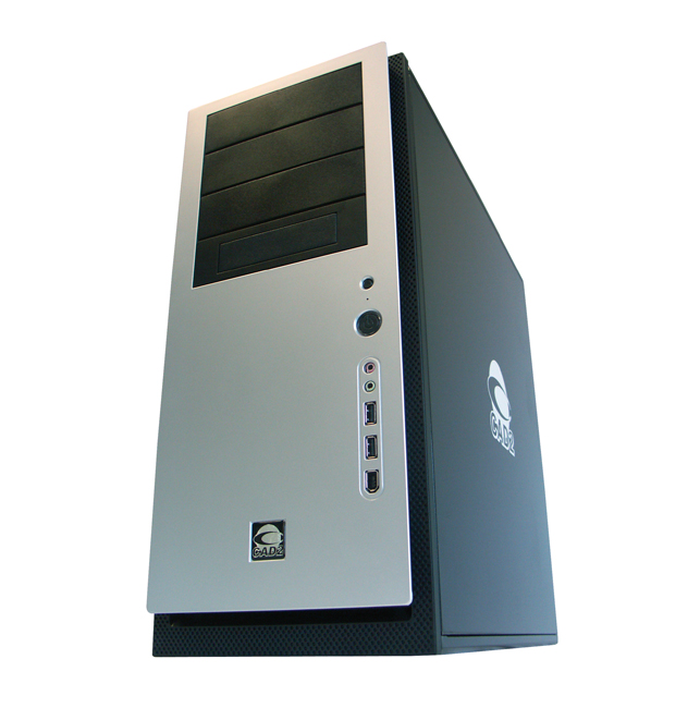
Comments on this article: