

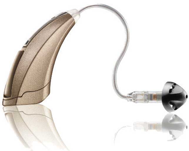
Most of us are familiar with traditional hearing aids – unattractive beige, shrimp-like objects that fit behind the ear. They certainly aren’t much to look at and it’s no wonder that those experiencing hearing loss have a reluctance to wear something that so obviously shouts disability. Despite the extraordinary advances in hearing aid technology, the actual design of the device itself has not moved on.
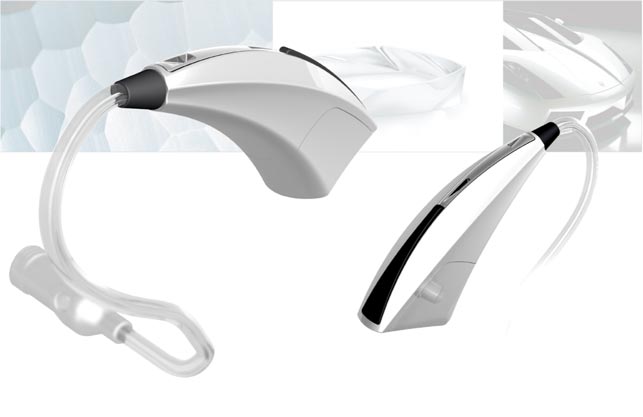
Starkey Laboratories, a global supplier of hearing aids, wanted to change that with the launch of the Zon. This sculptural 1.3-inch device, which fits discreetly behind the user’s ear, is almost jewel-like in appearance.
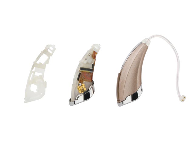
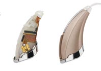
Electronic components are organised around an injection-moulded spine, which is inserted into the outer injection moulded nylon shell through an opening at the bottom
“Zon fills a real need in the market. Hearing aids have been a maligned product for years – they are costly, yet many of them pose technical challenges and there are few that visually communicate the value of the investment hearing aids require. Zon solves these problems on many levels,” explains Stuart Karten, founder of Stuart Karten Design (SKD), a Los Angeles-based industrial design consultancy that was involved in the design and development of Zon.
Starkey approached SKD to design the Zon due to the consultancy’s experience in ear worn consumer products, including the award winning BT-500 bluetooth headset for Jabra and the Voyager Pro headset for Plantronics. The brief was to package the core hearing aid technology and give it a form factor that would be ‘sexy in the hand and invisible behind the ear’. “Starkey came to SKD with a digital signal processing technology that was very advanced. It eliminates the feedback typical of most hearing aids, but the design had a long way to go,” explains Karten. “SKD’s goal was to express the value of this technology – the incredible value of restored hearing – on the outside of the product.”
Innovation through research
With the brief in hand the first thing the consultancy did was carry out extensive research. As part of this research the team immersed itself the hearing aid industry by not only studying competitor products but by attending trade shows, talking with hearing professionals and even studying Starkey’s own production and manufacturing capabilities. “Our designers even went so far as to build a hearing aid on the assembly line,” says Karten.
People will live in denial for an average of eight years before seeking treatment for hearing loss. If we could reduce that wait time the project would be a success’’ Stuart Karten, founder of Stuart Karten Design (SKD)
Of course, consumer research was extremely important and SKD spent a great deal of time with users by both talking to them about their hearing aids and observing them using them. “We conducted ethnographies and contextual inquiries in users’ homes, observing a day in the life of the hearing aid from cleaning and battery changing to adjustment and storage,” says Karten. “It was very important that our design team, most members of which are in their 20s and 30s, gained first hand empathy for the target customer, aged 65 to 80. This research is where some of our most poignant insights arose.”
For instance, they observed a seventy-year-old man trying to change the battery of his hearing aid whilst sitting at his dining room table. He confessed that if the battery dropped during this time, he would have no idea where it went because he wouldn’t be able to hear where it landed. So, the designers discovered that the tasks difficult for many users whose dexterity has been compromised by age, such as changing batteries or adjusting volume, were those areas ripe for innovation.
Form generation
Having conducted the research, the designers realised that their overall aim was to minimise the stigma associated with hearing aids. “We learned that people will live in denial for an average of eight years before seeking treatment for hearing loss. If we could reduce that wait time and make hearing aids a more acceptable treatment option the project would be a success,” comments Karten. Additionally, they wanted to ensure that the hearing aid they developed was new and different to what was currently on the market. Following brainstorming sessions they came up with the descriptors of “visually crisp and organic”, which would become the drivers for the hearing aid design.
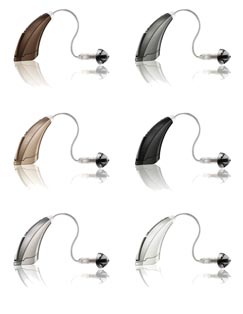
The Zon is available in six understated colours. The use of high-gloss metallic paint is designed to mimic the natural translucency and colour variation of hair and skin tones
Following the brainstorming sessions and having established the design direction, they began sketching their ideas and came up with ten initial concepts to present to the client, which were rendered using Bunkspeed’s HyperShot, a photorealistic rendering software. According to Karten, although they could have presented sketches or rough prototypes, HyperShot provides a high level of realism that helps the client envision the final product. During the presentation the chosen concept quickly emerged when weighed against the various objectives and criteria. “Its dynamic form was beautiful and provided the best wearing comfort with ample airflow and no ‘hot spots’,” he explains.
The chosen concept also incorporated solutions to many of the user challenges and needs identified in the research. For instance, the control button used to switch between digital modes and adjust volume is a single oversized push button along the hearing aid’s spine, where it is easily accessible in the worn position. Additionally, the battery door swings open from the side, allowing users to lay it on a table for additional support during the battery changing process.
Engineering collaboration
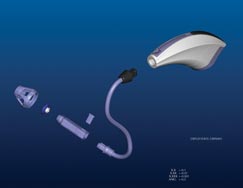
During the design process, SKD’s designers and engineers worked in close collaboration with the engineers at Starkey. The particular challenge of packaging all the components in the small space available was resolved by constantly sending Pro/Engineer CAD files back and forth between the two companies. The components that had to fit in included a pair of microphones, a battery and a hybrid chip. “The design was essentially modelled around these components, which determined the hearing aid’s size and orientation to a great extent,” explains Dennis Schroeder, SKD’s senior designer who was in charge of rendering and modelling Zon and collaborating with Starkey’s engineers to ensure the performance of the device matched the high level of design. Throughout all of this, careful attention was paid to ergonomics to ensure that the device would be comfortable and absent of hot spots.
Listen carefully

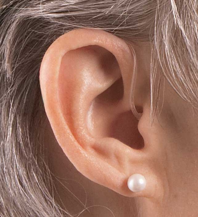
Spot the hearing aid: The Zon is incredibly discreet when worn
With one of SKD’s specific goals being to improve the Directionality Index – the hearing aid’s ability to clearly pick up sounds coming from certain directions – Schroeder and his team’s key engineering contribution was the location of the microphone port. Highlighted in chrome to delineate its function, the port was placed so that the microphones are horizontal on the user’s ear. “Starkey mentioned to us that the best way to improve directionality was to have the microphone ports line up parallel to the ground when in the worn position, ensuring that each of the two microphones are receiving sound from the same direction in front of the user,” says Schroeder. “By incorporating this principle into the design, SKD helped Starkey improve the Directionality Index of its new hearing aid by 30 per cent.”
Design for manufacture
Early Zon concept model produced inside Pro/Engineer
SKD also introduced Starkey to an innovative manufacturing process that would allow Zon to be assembled without parting lines or internal ribs and bosses, giving the device a smooth surface quality and a level of water resistance.
The process demonstrated how the shell could be manufactured from a single piece instead of two plastic pieces screwed together. “Electronic components are organised around an injection-moulded spine, which is inserted into the outer injection moulded nylon shell through an opening at the bottom of the piece. The microphone port cover and battery door are then attached to procure the spine in place. This process allows Zon to be assembled without parting lines, lending a clean, unified appearance,” explains Schroeder.
Colour me beautiful
In order to answer the brief of being ‘invisible behind the ear’, colour selection and materials played an important role in the design. “SKD studied hair and skin tones, talking with make-up specialists and Beverly Hills hair colourists. We learned that natural hair and skin is made up of varying shades,” says Karten. As a result, SKD developed a palette of six understated colours that complement both hair and skin tone.
“To make our recommended colour palette even more realistic, we encouraged Starkey to use high-gloss metallic paint to mimic the natural translucency and colour variation of hair and skin tones, helping the hearing aids to blend behind the ear better,” continues Karten. This was achieved by using a new paint strategy on nylon resin, which is a very strong and chemical resistant material. “We connected Starkey with Phillips Plastics who helped make this a reality,” says Schroeder.
Refined design
Having carried out further research and testing with the prototypes in order to validate the product design, the model was then refined in Pro/E. The designers found the high level surface modelling and skeleton model functionality of Pro/E particularly beneficial.
“Pro/E allows you to attach multiple parts to a master model or skeleton and these parts travel together. For example, when you resize one part, Pro/E automatically adjusts the connected parts to the same scale so that you don’t have to manually re-size them. This was very helpful on Zon because the model had six different parts,” explains Schroeder.
As Starkey has its own manufacturing and assembly facilities, the CAD data was then sent directly to the company to produce and assemble the parts.The Zon hearing aid was launched in mid 2008 and certainly meets Karten’s aim for a design that is both crisp and organic, a fusion between the human and the mechanical.
The project also brought much enjoyment to the consultancy. “We’re happy to have a client as open and collaborative as Starkey has been. We worked directly with the company CEO who sees the value that design can add and allowed SKD to be involved at a deep level, from foundational and user research to the complete product experience-packaging and retail displays,” says Karten.

HyperShot enabled SKD to give its designs a high level of realism and help the client envision the final product
Since the launch, Zon has not only been praised by users and hearing aid professionals but has also caught the eye of the design community, one such being New York’s Cooper-Hewitt National Design Museum that presented the consultancy with an award in the People’s Design Award category at its annual National Design Awards gala.
This category allows the public to nominate and vote for their favourite design. As Cooper-Hewitt’s director Paul Warwick Thompson said at the awards, the success of Zon demonstrates that good design can indeed have a transformative impact on our everyday lives. Although SKD have received many design awards in the past, this was a special award for Karten. “To take a product that no one wants and banish that stigma is an accomplishment I’m very proud of,” he says.
However, the collaboration with Starkey doesn’t end there and SKD’s next product for the company is due out at the beginning of 2010. It uses the same design language as Zon but in a larger, more powerful hearing aid. “This new product builds upon our initial user research, introducing a new user interface that further simplifies the process of adjusting controls. SKD has done additional research programs for Starkey on hearing aid accessories, docking stations and remote controls. More products are currently in development,” reveals Karten.
www.kartendesign.com / www.starkey.com
The hearing aid transformed by Stuart Karten Design


