

High roller
The flakes in corn flakes, the toffee in chocolate bars and the oats in porridge have all probably been flattened, rolled or otherwise processed by equipment from A.T. Ferrell.
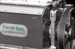
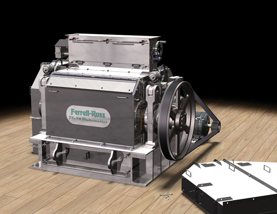
Just add milk: Ferrell-Ross flaking mills are used to make thin, flat flakes out of pieces of seed. These machines help put breakfast on the table of millions of American families every day
The Indiana-based parent company has been serving the agricultural, food and industrial markets since 1869, manufacturing rollers, flakers, and cracking mills responsible for producing some of the world’s biggest brand breakfast cereals.
A.T. Ferrell design engineer and CAD manager, Allen Gager, is currently working on a new high capacity cracking mill to be used for cracking the shelled grains.
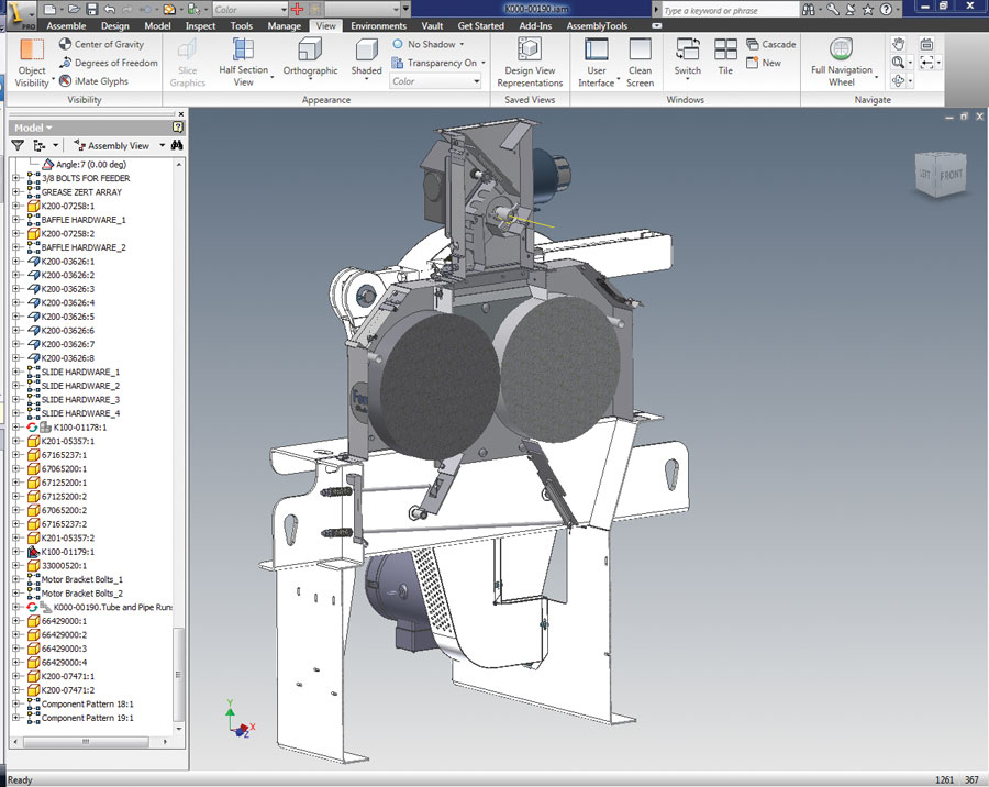
The team works with Autodesk Inventor, using its parametric modelling and finite element analysis capabilities to design machines that can work under high-pressure conditions while meeting all the necessary tolerance requirements.
According to Allen, with livestock prices falling and grain costs rising, the performance of the machine is critical to the end user. “Our products are engineered to be reliable and perform year after year,” he says, adding that by using a 3D CAD model the design team knows how a mill will perform before it is built.
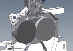
Designers at A.T.Ferrell create 3D models using Autodesk Inventor
“Using Inventor software to create a 3D digital prototype means we no longer have to cut metal to prove the feasibility of a design,” continues Allen, stating that by modelling the product they save greatly in getting the product to manufacture.
“It would be safe to say the design cycle of these projects is cut in half as a result of working in 3D.”
Additionally Allen and his team use Autodesk Vault Workgroup as a means to keep track of the design process and to improve the ability to reuse designs and components.
Overall this speeds up the development of new products and ensures that breakfast is on the table.
Best of lock
Fortress Interlocks designs and manufactures safety access systems from its new factory base in Wolverhampton.
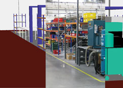
Fortress Interlocks proves out its assembly lines by creating fly throughs in Pro/Engineer
Far from everyday locks, these are for industrial situations such as switchgear, nuclear power stations and automotive plants – all of which are hand built in a prebuilt factory building along an assembly line, the layout for which was proven in 3D.
“We did the layout in the traditional way, with bits of paper, then that was transferred into 3D CAD where we could do a fly through video so we could get an appreciation of what the place would look like,” says operations director Simon Bailey.
Using Pro/Engineer, the same system used to build the product models, the team sets about transforming the 2D sketches into a 3D model. This was rendered in the same program, and a flythrough video was produced.
It was key to make the workplace organised and comfortable for the staff to move into. “When you’re moving factory, it’s the getting the shop floor people involved in the process [that’s important],” says Simon.
“You have to have some way to show them what they’re going to get, in a way that they can understand.” The flythrough proved key in helping decide on the workflow layout of the shop floor and the series of benches that form the assembly line.
The new factory is now up and running, and with all workflows previewed in a 3D model the company was locked in and ready to begin production with the minimum of disruption.
From the ground up
Hyde Group is a key post-production component supplier for the aerospace industry, using 3D CAD models not just to build parts but also the entire factory process.
Supplying Airbus, BAES, and Rolls-Royce, the firm builds composite materials for ‘future wing design and development’, with techniques developed to create single-piece wings up to 20 metres in length.
The skills and capability to design and manufacture in composite materials are vital in the aerospace industry, so a bespoke engineering solution is needed to meet the challenges the material poses and the growing demand.
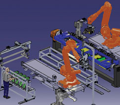
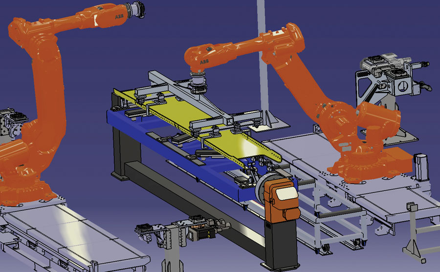
The production line at Hyde Group is capable of producing 40 sets of wings per month
“Traditional build systems used for aluminium wings are unworkable for carbon fibre wings so a modular approach, using robot technology and ‘off-the-shelf’ automotive-style flowline solutions, is being perfected for this application,” explains Hyde Group technical director Richard Waring.
The company works with Dassault Systèmes’ Delmia software in order to design a factory floor in 3D that can fully simulate a process of robotic systems and human input capable of producing 40 sets of wings per month.
“Pulsed manufacturing methods are optimised using Delmia V5 R19 and Delmia Automation with component handling and mechanical operations fully modelled and simulated in kinematic 3D. By taking a modular approach, using robotic systems, manufacturing flowlines are developed.
“Operational sequencing and full simulation of robotic activity allows us to programme the robots and indeed design the whole flowline at the outset of product design,” says Richard.
Production programming, as part of a full design process, means that costs and waste are minimised, and helps ensure that the as yet to be built factory need not take up any more space than needed.
This all-encompassing approach means that 3D CAD models are literally used from the initial product part designs, right down to the factory floor they are to be built on.
www.hydegroup.com
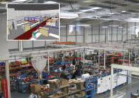
Taking a look at the design on the factory floor


