Objet Connex350

28 August 2009

Process type: Prototype

Objet Geometries has just launched a smaller form factor and lower cost version of its Connex500 3D printer, a machine that can make models out of materials with different mechanical properties in a single build. Al Dean takes a whistle-stop tour

Product Connex350
Company name Objet Geometries
Price on application

When Objet Geometries launched the Connex500 earlier this year, it introduced an entirely new concept to the 3D printing sector - the ability to produce a model with different mechanical properties.

The machine worked by mixing two master materials in different ratios on the fly to create any combination of rubberlike, flexible and rigid parts with different visual appearances and shore hardnesses. Most importantly though it was possible to do this in a single build.

The combination of rubberlike, flexible material and rigid material allows users to print models for a wide variety of applications

The younger sibling

Objet has now introduced a new machine, the Connex350, which features exactly the same core technology, but in a more compact unit, with a smaller build tray size (350 x 350 x 200mm compared to 500 x 400 x 200mm). This reduction in size is also reflected in the price of the system, making it much more affordable for a wide range of users.

Having seen the Connex350 in action at Dassault Systèmes’ recent DEVCON event at its headquarters in Paris, the machine looks very office friendly. Around the size of a standard photocopier, but much more stylish in its appearance, the office friendly credentials are earned through the use of completely sealed material cartridges. These are loaded up with ease and getting the machine ready to print doesn’t take a great deal of effort.

As with the Connex500, the quality of the models created with the Connex350 are amazing. Very fine layers of 0.016mm thicknesses are combined with high-resolution printing in the X and Y directions to deliver models of impressively fine detail. And by taking advantage of the many material choices on offer it can be used to generate models with the required look and feel of actual end products. The combination of rubberlike, flexible material and rigid material allows users to print models for a wide variety of applications, from coating and shock absorbers to living hinges and gaskets - and it excels at replicating the feel and tactile response of over moulded or multi-stage injection moulded components - something which is very time consuming and labour intensive to prototype using vacuum casting.

Connex 350

With a smaller build tray size of 350 x 350 x 200mm the office friendly Connex350 is the younger sibling of the Connex500

Conclusion

The decision to acquire an in-house rapid prototyping technology is a choice that most design-led organisations don’t take lightly. After all, investing in a machine can be expensive, particularly when you consider the on-going costs of maintenance and materials supply. Alongside the cash costs, there’s also the constant nagging thought that by investing into a single technology, you’re excluding others - putting all your eggs in one proverbial rapid prototyped basket. This is exactly why the Connex350 is so appealing. In comparison to the many other office-friendly 3D printing devices, it offers increible flexibility in terms of the mechanical properties of builds. And as such, if you are evaluating these tools, then it should certainly be flagged up for further investigation

www.objet.com


Integrating Rapid prototyping and CAD

Helping bring the worlds of 3D design and rapid prototyping closer together, Objet has recently launched a number of ‘CADMatrix’ plug-ins that enable users to control builds directly from within their 3D design system.

CADMatrix

Objet has recently launched a number of ‘CADMatrix’ plug-ins that enable users to control builds directly from within their 3D design system.

There are plug-ins for SolidWorks (pictured left), Inventor and Pro/Engineer), and having given the SolidWorks and Inventor versions a test drive, it’s clear that they can greatly assist those working with these machines in house.

The plug-ins allow users to select parts or assemblies, materials, the machine to build on, coatings (to achieve a soft touch on a rigid material), and then have the system generate the required file for set-up and printing. The system then creates STLs from the CAD geometry to the required accuracy and even provides an HTML report when it’s complete, so users know which parts are going to be built and which materials need to be loaded into the machine.


Comments on this article:

TurboCAD 16.0

28 August 2009

Process type: Design

Al Dean looks at TurboCAD, a stalwart in the world of 2D CAD, and wonders if the implementation of new technology adds real value to those looking to design in 3D?

Product TurboCAD 16.0
Company name IMSI
Price from £895

The benefits of working in a 3D environment are well documented and established. So, why are we taking a look at TurboCAD? The answer is that despite all of that lovely 3D action, sometimes you need a more simple tool to sketch out ideas and to edit legacy drawings. This is exactly the space in which TurboCAD has been operating for many years. What’s intriguing is that the developers have incorporated the ACIS 3D modelling kernel and the LightWorks rendering engine, meaning that alongside the wealth of 2D design tools, TurboCAD has been upgraded to 3D. So let’s take a look at where it might fit into your processes and workflow.

TurboCAD is very capable at creating 2D engineering drawings or editing existing, legacy data from a variety of formats

IN USE

TurboCAD’s user interface harks back to the good old days of 2D CAD. The majority of the screen is taken up with the drawing area, while the periphery features a range of pull down menus, a vast array of toolbars and, to the right hand side, a tab panel that provides access to commands, options, and libraries of standard parts, blocks, rendering materials and environments.

As with all 2D-focussed systems on the market today, creating the drawings, whether for production or just to get some ideas down on paper, is a lengthy process. While TurboCAD has a full range of geometry types, from the usual array of lines, circles, arcs and splines (and now pushing into the creation of 3D geometry), what’s missing, in comparison with many of the sketching tools within mainstream 3D modelling systems, are things like inferred constraints and relationships which make life much easier. That said, grids and snapping tools are available once templates are set-up correctly giving you a helping hand. The Professional Mechanical version is also supplied with a limited range of 2D and 3D fasteners, such as nuts, bolts, other hardware and a few standard engineering forms, such as beam sections. These are dragged/dropped from the right hand panels and reused as and when required.

Data Import

When it comes to importing 3D geometry, the system has a good range of options, from 2D standards such as IGES and DXF, plus other native formats, such as DWG. In terms of 3D file import, it supports IGES, STEP, STL ACIS, 3DS, SketchUp, and OBJ.

Importing a 3D file into TurboCAD’s model space initially gives you a wireframe representation of the part, but a quick rotate of the model and hitting one of the rendering options shows that you indeed have a full 3D part. This can be worked with to some extent to set-up work planes onto which to add dimensions and such.

TurboCAD 16.0

The integration of the LightWorks rendering engine means that if you don’t have rendering technology in house, you can have access to it through TurboCAD

Working in 3D

TurboCAD’s 3D functionality is much more atuned to the world of architectural design. While the promotional material and web-site shows that the system is being used for mechanical design, I found anything other than basic part design quite hard to do. In terms of 3D functionality, if you compare the system to other products on the market at the same price point (I’m thinking specifically Alibre, SpaceClaim, and IronCAD’s Inovate), the tools really don’t stack up in terms of being able to dive in and generate 3D product designs. You may be able to create the same 3D geometry, but the process is likely to be lengthy and inefficient. And when it comes to making design changes, it can be hard work.

Cost

TurboCAD Professional costs £895. If you then want the add-ons for mechanical design, you basically add sixty quid, topping out at £955. If you want the architectural add-ons as well, then TurboCAD Platinum, (with both add-ons) sees that price rise to £995 per license.

Conclusion

Where does TurboCAD fit into the product development process? The system offers a good, solid alternative to other 2D CAD applications, giving you a full range of detailing tools for creating new drawings from scratch or editing legacy work. But when it comes to 3D, designing from scratch or editing 3D data, even with the introduction of ACIS, it doesn’t quite cut it as a workhorse 3D design tool. As a result, TurboCAD is best applied to its original purpose of creating and editing 2D drawings, and for occasional 3D work, possibly for presentations using its LightWorks rendering engine.

www.turbocad.com

Comments on this article:

Dezineforce

28 August 2009

Process type: Simulate

As the complexity of simulation increases, many users are hitting bottlenecks in terms of processing. Al Dean looks at a new online service designed to be a cost effective alternative to buying a super computer

Product dezineforce
Company name dezineforce
Price on application

Simulation, whether that’s Finite Element Analysis (FEA) or Computational Fluid Dynamics (CFD), is very processor intensive. The advent of eight-core workstations has put more power on the desktop, but simulation-led organisations with complex problems need more performance and distributed cluster-based solutions with 100s of CPUs are common. The problem is, even in today’s world of low-cost hardware, clusters can be expensive, not only in terms of capital purchase, but on-going maintenance. This is where remote computation or as the IT industry likes to call it, Cloud-based computing fits in, and leading this charge is an organisation called dezineforce.com.

Dezineforce offers a service that enables customers to run their design processes on remote high-performance computing clusters. While this is nothing particularly new, there are also some incredible value adds, specifically in terms of optimisation which lead to reduced design cycle times.

A response surface created using real data from a multi-parameter optimisation study

Genetic algorithms are used to carry out a wide-range of optimisation studies in a fraction of the time traditionally taken to explore vast numbers of combinations/iterations. This is done through ‘evolutionary optimisations’ which start with a random population, create ‘mutations’ based on user-defined success metrics and ‘breed’ them until the strongest candidate is found. Alongside this, there are other, more commonly known optimisation methods built into the dezineforce platform (such as Gradient, Hill-climb and Design of Experiments techniques) and a broad, ever expanding range of pre-set workflows for the most commonly performed simulation tasks.

The system is accessed through a web-based interface, in which the user defines the workflow, variables and the mesh to support the simulation. Controls for any optimisation are then defined, alongside convergence requirements and the actions for results handling.

As the job moves forward, its progress can be monitored, and the user can cancel it if problems are found (the usual log-file is available from the various solvers). Email notifications can also be sent as jobs are completed or limits are reached.

Dezineforce is sold on the basis of an annual or project-based subscription, tailored to need, and that subscription can take several levels - but the key concept is the number of computation hours available each month. The stopwatch starts only when the process itself is running. The setting up process is not charged for.

In terms of how many hours you will typically need, the answer is as long as the proverbial piece of string. It depends on the type of analysis you are doing (CFD is more compute heavy), the size of the design team, the nature of the problem (linear or non-linear), and how complex the optimisation parameters and variables are.

Dezineforce

Example of dezineforce results visualisation tool, used to aid understanding of results of optimisation studies

The interesting thing about dezineforce is that in addition to being able to throw an incredible amount of compute power at a problem, the optimisation techniques used (particularly the evolutionary methods) can greatly reduce design cycle times. This is done by cutting the number of solves needed to explore a complete design space, and using informed and intelligent decisions to decide which avenues to pursue.

The beauty of dezineforce is that it encourages the use of simulation as a key driver for design exploration. By speeding up the simulation process better design decisions can be made, faster, based on more complete exploration of the design space and that can only benefit the end product. Dezineforce is not a cheap service, but for those serious about optimising their development processes, it’s certainly worth closer evaluation


www.dezineforce.com


simulation software support

Dezineforce works with virtually all the leading lights of the simulation world.

In terms of pre/post processor, the list includes Gambit/TGrid, ICEM and Ansys Mesh from the Ansys/Fluent stable, Patran from MSC, Primer from Oasys and Catia.

For Computational Fluid Dynamics (CFD) it works with Fluent and CFX, and for FEA, Ansys Mechanical and Rigid Dynamics, AutoDyn, MSC.Nastran, MARC, Adams and LS-Dyna.

Comments on this article:

Vuuch

14 August 2009

Process type: Collaborate

Josh Mings previews a new tool that co-ordinates design discussions on the Web and directly inside your CAD application rather than being spread out and disconnected across email, conference calls and meeting note

Product Vuuch (beta)
Company name Vuuch
Price Free trial

There’s a critical metamorphosis about to change the way we communicate during design. You may sense it with each email you receive, each search you perform, and within the meetings where everyone scurries to make notes. This transformation is about moving critical design discussions into your design tools, making it a coordinated effort across the design team and into web interfaces where anyone can become a part of the process. The catalyst for this is Vuuch and it’s set to affect the whole landscape of how and where we discuss design.

If we didn’t have email, our lives would either crumble to bits or we would actually have a more productive day.

Vuuch

Vuuch currently supports Pro/E and SolidWorks, but development is under way for other design applications

Email is as pervasive a communications tool as you can get, but as convenient as it is, it’s all too often the cause of information loss and people left out of critical conversation. While I’m sure some scientist would say email is the cosmic glue that holds everything together, I’m going to raise my fist and say, email is a dead man walking… or at the very least turning into something that will be much less useful. In its place is a platform called Vuuch that combines the best aspects of email, Social Media and Instant Messaging delivered through a simple set of web and embedded clients.

What Vuuch does


Vuuch (pronounced Vooch) quite simply allows you to centralise and preserve design discussions. Instead of decisions being spread out and disconnected across email, conference calls and meetings, Vuuch keeps the content about the design consolidated within the design environment and on a web portal called vuuch.me.

The software is currently in beta release with full development taking place for various platforms including Pro/E Wildfire 4.0, SolidWorks 2008 and later and Excel 2007, with more being planned. The single identifier throughout everything with Vuuch is its simplicity. The add-in installs easily and immediately allows you to begin creating discussions within the interface you are using.

There are several ways to view and create discussions within a design environment. Typically, it will happen by selecting a model, a feature or a sidebar icon that allows you to view discussions started by yourself or others.  After starting a new discussion you simply use the tabbed discussion window that appears to enter information as you would if typing details about a design change into an email. You select another tab to invite participants and the discussion begins.

Beyond Email

With a strong argument that Vuuch is here to reduce (if not destroy) the excessive amount of email traffic we receive, you may be interested to know how it compares with email. As it stands, Vuuch doesn’t allow you to perform a lot of the functions you have through email, like attaching a 50MB PDF or grouping emails into groups of folders. Then again, email doesn’t allow you to select an object within a design environment and start an interactive discussion about it, as Vuuch does.

With email, you can start online meetings, check spelling and insert images and tables. Vuuch doesn’t offer any of those features yet. Email applications (besides the free online type) are not web-based. Vuuch is a web-based solution, but beyond that it filters your discussions based on what you are working on and displays them right within your work.

Vuuch

Users can access and discuss designs directly from within their CAD application

With email, you switch back and forth between programs and folders to get to files you need to attach or screenshots you need to embed. With Vuuch you simply stay in the application you are using. On top of this you can interact via the web portal and even email. Yes, the very tool that often drops us into a communication abyss is where a lot of discussion about the design can happen. However, this allows you to add to the discussion when away from your workstation with a direct reply to emails about the discussion you’re a participant of. People in the design environment can see the comments and anyone on the web portal can also see and respond to the activity taking place. It captures communication at multiple points and converges it all into one discussion.
 

Aiding design

Your design applications are void of discussion. It happens outside in a disjointed set of tools that know nothing about product development. We sit spinning models around, discussing what to do next and forget that everyone else isn’t included in the changes about to occur. Vuuch cuts into the middle of this to allow design groups, or anyone involved in the process, to have one location to see how decisions were made, and one location to discuss them further.

Whether you’re working with a customer directly or talking with vendors to spec parts, anyone that needs to be involved can be. This is catapulted by the ability to join in a conversation from anywhere through the web interface or email. Vuuch can be used to make notes of problem areas, track daily status or coordinate build cycles with production simply by allowing people to become part of a single discussion.

Vuuch

Vuuch keeps the content about the design consolidated within the design environment and on a web portal called vuuch.me

Vuuch gives you back the countless hours expended formatting and organising your email. In addition to giving you more design time, it adds value to the model by preserving the design discussions as part of the model definition.  Days, weeks, months and years later your design decisions are still available. But what if the model isn’t open? What about the aspects of design that happen away from the computer - the bidding, idea stages, conceptualising, and drawing checks? These areas are even outside the realm of email, captured in photos, video, clay, cardboard or other media. While it’s seemingly disconnected from the area where Vuuch provides the greatest benefit, they can still be included as part of the discussion and referenced from within the design environment being used. 

Conclusion

Is it possible to capture all the discussion that revolves around a model, that is part of a task, that is part of a larger project? It’s easy to think that throughout all the applications we use, some discussion will not get captured. It’s also easy to presume that email will always be the best tool to transfer information. The developers of Vuuch are in the process of addressing this by releasing their open API which will allow discussion to be brought into other applications whether they be on your computer, on the web, or on your mobile.

Vuuch is limited right now, but let’s face it, a lot of discussion that happens doesn’t require the excess features that email has or the complexity and cost of project management software. This is good, in my opinion. Instead of trying to completely emulate how email works and put it inside a CAD or web interface, the developers are letting users provide feedback for what they need. However, the development going on with the CAD platforms is only one aspect. This technology could very possibly reach into the environments of social media and other web applications. Perhaps even some of it will be used online for design or product sales and service. And hey, why not Vuuch-enable your ERP system to capture the discussions that are related to a customer service call?  Wouldn’t it be great to reuse this in design or when a similar problem occurs? Once you put a symbiote of an idea into one area of design it can affect the entire lifecycle of that product.

With an open program interface and web interoperability, Vuuch has the potential of being an application that allows interactive discussion to take place anywhere. There are big changes coming to design environments and Vuuch is adding an aspect of collaboration that hasn’t been seen in CAD or any other type of design before. It is taking away the limitation that email has on us and it all starts with a single united discussion. Vuuch lets you do what we are used to doing, send a message, and at the same time it creates a huge value without the user having to do anything extra.

Comments on this article:

Inventor Fusion tech preview

14 August 2009

Process type: Design

DEVELOP3D’s editor Al Dean  gives his first impressions of Autodesk’s brand new direct modelling technology preview. Now available to the general public as a free download, the software represents a promising opening move

Product Inventor Fusion Technology Preview
Company name Autodesk
Price Free for download

Representing Autodesk’s first foray into the world of direct geometry editing, Inventor Fusion is arguably one of the most eagerly awaited technology launches this year. First shown at Autodesk University in Dec 2008 where we got the scoop on DEVELOP3D.com, the technology is now available for free download from the Autodesk Labs web-site.

Out of all the CAD vendors, Autodesk has one of the most impressive Labs sites and many core parts of Inventor began as Technology Previews, just as Fusion has now. It is likely to remain in Autodesk Labs for some time as each successive public release is put out for all to see, play with and give feedback to help drive its development - so let’s take a quick look at what all the fuss is about.

LESS IS MORE

The Inventor Fusion user interface is minimal to say the least and because it has a small set of commands view manipulation is pretty much standard as in Inventor 2010, with keyboard shortcuts for pan/zoom/rotate as well as the ever-present View Cube and Navigation bar to give you quick access to view settings.

Autodesk Inventor Fusion

Unlike Inventor 2010, Inventor Fusion doesn’t rely on history. Features are still very much an intrinsic part of the application, but it doesn’t carry with it the headache of history recalculation when features are edited

The familiar browser is integrated into the user interface, rather than as a separate panel and gives access to named views, origins, work geometry, annotation planes and a feature list - but no history and this is key, as Fusion is a history-free modelling technology.

The user experience is highly dynamic with less reliance on toolbars and menus. This is a heads up interface to the extreme. Much of Fusion is driven from marking menus, something that was introduced into the Alias products many years ago and adopted by many modelling packages as a replacement for the context sensitive right hand mouse button menu. Fusion combines the two. Hit the Right Mouse Button (RMB) and a marking menu pops up along with a more traditional menu. This provides access to all of the commands you’ll need - the most important found on the marking menu while the traditional menu gives you a fuller, context sensitive selection.

The sketching workflow in Fusion is very slick. Informal dimensions are placed on the fly, and users can snap and infer relationships while hitting values locks them down (typically for length and angle, using tab to toggle between the two). One thing to note is that Fusion defaults to inches. To switch it to mm, hit the scale key at the bottom right of the screen.

As with most direct modelling systems, there are only a handful of major operations. Press/Pull and Move are the predominant ones. Press/Pull is used to create extrusions, either to add or cut material. Hit the command, select the profile and the display brings up a preview and a small arrow. Geometry can be dragged to the desired depth or values keyed in. With the small glyph near the feature, you can define direction around the plane and a small ball can be used to create the required draft angle when dragged. If you use the Press/Pull command with edges, then you’ll switch to creating fillets.

Autodesk Inventor Fusion

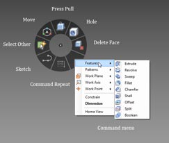
The Marking Menus provide access to the most commonly used commands around the cursor and a secondary, more comprehensive list of commands are found in a more traditional menu

While the Press/Pull command is used in most instances, the Move command lets you work with existing geometry, grabbing the geometry, for example and using a triad to move or rotate sets of faces. The axis can be locked to specific planes, axes and angles, and using the F6 key, you can also shift it to other reference geometry (such as an edge to get a planar move reference).

Alongside the Press/Pull command, there are familiar commands for sweeps, revolves, fillets, chamfers and shell. There’s a Delete Face operation, but it’s worth noting that the system will only allow you to delete a face if the removal of that face results in a watertight model, once the boundaries have been filled in. There are also patterning tools (radial and linear), mirror of features and part splitting.

Assembly modelling

Alongside the part modelling and editing tools, Fusion also allows you to create assemblies using some basic mating tools. As the system is ‘multi-body in a single part’ capable, you can work with both explicit separate parts or use the same alignment and mating tools to build up an assembly using multiple bodies. Found when clicking the Constrain icon in the Home panel, the basic commands are Align, Centre, Angle and Tangent, all with offsets where appropriate. One thing to note is the order in which you select your mating geometry. As Fusion doesn’t have a fix or Anchor command to lock the first part down, you need to remember that your first selection is automatically locked and the second selection moves to it.

Working with Imported data

Inventor Fusion will read native Inventor data directly but will only import solid data and doesn’t yet support assembly features (such as weldments). In terms of third party data, Fusion supports the importing of SAT files (between version 4.0 and 7.0) and STEP files (supporting the AP214 and AP203E formats). For export, it’ll save out to Inventor format but the other formats are limited to SAT (7.0 only) and STEP using the AP203 standard.

While Inventor Fusion is a non-history-based application it still takes advantage of feature-based working methods. But what about imported data that typically doesn’t have this feature data? To add some intelligence, Inventor Fusion has basic feature recognition tools built into it. Once you have your geometry imported, run the Recognise Features from the Home panel. This interrogates the part and will find any hole, fillet or pattern features and store them in browser. It should be noted that this does not replicate the native features but rebuilds those features that Fusion can work with. The same is true of importing Inventor parts, you won’t get a replication of the native feature tree.

When it comes to making changes to parts, I’ve found it’s best to dive in and work with the data directly, using a combination of the Press/Pull and Move command to edit the geometry, shift it and work with it. When working with direct modelling tools such as this, it is important to realise that all systems have quite specific limitations in terms of topology. While you can move, push and pull faces seemingly at will, the model must remain watertight and closed and the geometry/topology must solve. When you see faces disappearing, this is usually in the area of fillets, where the underlying modelling engine can handle the removal of those faces and patch the surfaces back. Make too drastic changes to complex geometry and you’ll run into trouble. The good news is that Fusion gives good feedback about what the system can do and will clearly flag up problems.

Autodesk Inventor Fusion

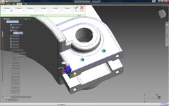
Using the Move Triad and the F5 key allows you to grab geometry, align the triad to the required direction and pull it into position

Summary

Looking at this initial Tech Preview, it’s clear Inventor Fusion is an exciting technology, but there are still many things it can’t do, particularly when compared to other direct modelling systems. One omission is the round trip functionality that was shown at the official announcement earlier this year, where feature data can be maintained between traditional Inventor and Fusion. However, Autodesk is very transparent about the current limitations and a list of things it can’t do is installed with the software, so if you have problems, check that first.
To be frank, I’m in two minds about what to write in the way of a conclusion. This is very early stage software, nowhere near production ready. The technology is going to have the rough spots knocked off before it gets anywhere near integration into core Inventor - which is the eventual goal, rather than a standalone application. So let’s strip it back to basics and look at what Fusion represents.

The most immediate things are the direct modelling tools that allow you to work with geometry in an effective manner, regardless of source. They follow the conventions of other direct modelling systems and it’s clear there’s potential here. While direct modelling is never going to replace history-based modelling, it’s well suited to pure, hardcore modelling operations where history-based systems fail - whether that’s working with imported, dumb data or making design changes at late stages where model history becomes unwieldy. It also provides an interesting way for the non-expert CAD user (but I’d stress the experienced engineer or designer) to get ideas down, play with geometry and to think in true three dimensions - but without the knowledge overhead associated with history-based techniques. These have been the sweet spots for direct modelling for the last two decades and I suspect might always remain so.

What’s changed is that there are now larger vendors jumping into the space that’s formerly been occupied by the likes of CoCreate and IronCAD. If you have bigger players making a lot of noise, there’s a perception that something new has been discovered. The fact is direct modelling isn’t a new concept. What’s changed is market awareness, increased development resources and more powerful hardware to enable those direct edits to be made with less chunking of a processor set.

Alongside the direct modelling, there’s something else afoot with Inventor Fusion and that’s an intriguing experiment or testing of waters with regards to the user interface. Looking at Fusion and separating the modelling technology from the user experience, it’s clear that Autodesk is testing out how users react to the new marking menu system, a much more interactive heads up way of working than is currently implemented in Inventor 2010. What I find intriguing is that Autodesk is doing this by releasing code into the public realm and letting users (whether they’re customers or not) play with it and see what it can do. That can’t do anything other than assist with making a better product.

The two in combination certainly make for an interesting development. Some new technology that’s at a very formative stage, still awaiting some of the core components, and which is going to extend well beyond this calendar year with updates. Let’s see where it goes.

.(JavaScript must be enabled to view this email address)

Comments on this article:

Latest D3D jobs

Design Engineer

Thu, 09 Feb 2012 07:32:39 +0000

Design Specialist/Engineer

Thu, 09 Feb 2012 07:30:23 +0000

CAD / CAM PROGRAMMER

Thu, 09 Feb 2012 07:09:07 +0000

Project Design Engineer

Mon, 06 Feb 2012 10:44:52 +0000

Tags for
this article