Solidworks 2010
09 October 2009
Process types: Design and Visualise
The 2010 version is an important release for SolidWorks. While not brimming with new features, it’s the enhancements to existing commands that will make the real difference, writes long time SolidWorks user, Josh Mings
| Product | SolidWorks 2010 |
|---|---|
| Company name | SolidWorks Corp |
| Price | from £4250 |
SolidWorks has been rockin’ out the updates since 1995 and over that period seventeen releases of the 3D product development software have emerged, each one with a little more 3D modelling power than the one before. Everyone who has used SolidWorks will tell you of a particular release they thought was the best. It’s likely to be the one that crashed the least or finally had that one special feature that they’d been waiting for.
Now, we complete the first decade of the new century. 2010. It’s a year where budgets are tight, expenses are stripped and upgrades for software are delayed. On many levels, SolidWorks 2010 has to be the pinnacle of releases. For SolidWorks development, for the businesses that use it, and for the user… it’d better be good.

The new assembly visualisation tool is like a parts list with a little pizzazz, allowing users to interrogate an assembly against different properties
The best new features
If you’re looking out for a lot of fresh new features in this release, you will cry a small puddle. Compared to previous versions, SolidWorks 2010 puts more focus on increasing the options of the existing commands. I’m hearing shouts of ‘hoorah’ from the crowd. Yes, that’s a good thing and definitely welcome, but more on those later. Of the new features there are two you’ll definitely want to use - mouse gestures and assembly visualisation.
With SolidWorks 2008 there was a recognisable shift from the standard toolbars and pulldown menus to on-screen command access via the Shortcut toolbar. As controversial as the changes were, it laid the foundations for a brand new workflow. SolidWorks 2010 takes this further and introduces a gesture-based menu system.
Rather like the shortcut bar it’s an on-screen menu designed to provide access to commands a little faster. It’s fully customisable, appears in each environment of SolidWorks from sketches to drawings, and is accessed with a right-click and slide of your mouse in one of eight directions.

The mirror components feature is substantially improved and not only makes it easier to create opposites of components, but also keep their constraints
Those familiar with Maya marking menus or the Opera browser’s mouse gestures will know just how useful gestures can be as a way to access commands faster. However, they’re not the most visible way of accessing a command, and if you’re used to keyboard shortcuts, it’s more than likely that they’ll just get in the way. Nevertheless, it’s now possible to free the hands from the bonds of the keyboard, providing regular users, and the dedicated 3D mouse user, more access to commands throughout drawings, parts and assemblies.
While you’re mousing about in assemblies, the last thing you may want to do is visualise them in new and exciting ways, right? Yet that’s exactly what the new assembly visualisation tool allows you to do. It may seem like a useless feature at first, but there’s more to it than just pretty colours. It allows you to interrogate the assembly against different properties you have set up.
Say you want to reduce waste or cost, you can use assembly visualisation to filter for such properties and quickly identify which components are guilty. It’s like a parts list with a little pizzazz and a feature that can be used when working with manufacturing or design to optimise parts. These are just a couple of the new features simple enough to bring into daily use, without the dreaded fear that one would cause parts of your model to fail horribly.
The improved features
While adding new features is nice, one thing users always ask for is existing commands to work better and this is an area that SolidWorks has concentrated heavily on. They’re usually updates that don’t look flashy in a review, but can, in fact, remove hours of frustrated workarounds. There are many in 2010 that directly aid in a user’s ability to speed up their workflow, but the ones we’ll focus on are a select few of the small tools you would use everyday.
Creating reference planes has been completely revamped to more than double the amount of possible configurations for plane creation. The new plane property manager now allows for 44 different combination of references, increased from a mere 18 in the 2009 version.
Materials can now be added to multibody parts and while the process needs further improvement it allows you more options for modelling weldments or reference parts. The mirror components feature gets a substantial improvement that not only makes it easier to create opposites of components, but also keep the constraints of the components that are mirrored. The settings and preview you get now actually makes sense and increased options allow you to create a derived configuration, break links or select a folder for mirrored components - easy and useful, just like it should be.
Perhaps one of the most useful updates is rapid dimensions. It could also be called ‘a better ways of escaping thoughts of suicide while working in drawings,’ but I guess that’s a bit long for a feature name! If you create a lot of dimensions on your drawings, take a good long sip of coffee and listen up, this is a huge time saver.
Rapid dimensions basically allows you to do a slow double-click to locate a dimension, instead of the typical click-drag-click. Don’t worry though, even though you’ll see it every time you place a dimension, the existing method hasn’t been removed. The downside is, it doesn’t work with ordinate or baseline dimensions, so you lose out there, but overall this simple solution to a repetitive task is a big bonus for the drafting drudgery.
Direct Editing in SolidWorks?
With all the buzz in the industry surrounding direct modelling or direct editing many are wondering if SolidWorks has these capabilities. Ever since companies like SpaceClaim, Siemens PLM, Autodesk and PTC started increasing efforts in direct modelling technology (efforts started long ago by companies such a CoCreate, KeyCreator and IronCAD) the race has been on to see who is going to make the biggest impact.
You’ll read plenty of opinion on this modelling method and SolidWorks even has the stance that it’s not what the users are requesting. Yet, bits and pieces of direct editing jargon and workflow keep slipping into each release.
What SolidWorks has built in the past with Instant3D and face manipulation features has hardly been considered direct editing. You need dimensions or features that behave when you try to move them about. When we think of Direct Editing we picture a completely fluid form of modelling. The reality in SolidWorks is that it’s still very linear and rigid. However, from a history-based, parametric modelling standpoint, this works and the new features in 2010 show no sign of ditching the dimensions or the features that go along with them.
What you will see in 2010 is a new direct editing toolbar for the CommandManager and the move face feature added to the list of face commands in the right-click shortcut menu. The 3D triad also gets a little improvement - you can locate it based on selections and it has the nifty Instant3D style ruler to show how much you’re moving faces.
The move face feature is handy, particularly for surfacing where it, and the delete face tool, offers much improved rebuilding times in 2010. But for those adverse to adding more features and the additional rebuild time, using Instant3D is a much more straightforward method of moving geometry around - just remember to fully dimension your features.
All together, there’s nothing too fancy happening here, but as users start to see more of these features appear in SolidWorks, it’s fair to say that they will begin to request more usable direct editing functionality in the product.
New hardware technology
New ways of modelling mean little if the software cannot be hooked up into brand new technology. The year 2010 is going to be a bare-chested marker for many things. One of these, whether we like it or not, is a computer interface change.

SolidWorks 2010 introduces a gesture-based menu system
From 3D displays to multi-touch-enabled devices, we’re looking at the beginning of a major advancement in how we design. Based on what SolidWorks is introducing in 2010, the developers seem to be casually aware of it as well.
Within the main interface of SolidWorks 2010 you have the ability to not only use the mouse gestures mentioned above, but also multi-touch gestures on any touch-enabled device. Support is currently limited to standard and basic view commands, but you can bet there is research going on to see how this tech can best be used for full product development.
Autodesk Labs has been experimenting in this area and SpaceClaim, a history-free 3D modelling program, is due to launch a new version of its software which contains multi-touch capabilities for many of its direct modelling features. Mac and Linux already have multi-touch support. Windows 7, launching this month, supports touch-enabled hardware and software. Producers of capacitive and resistive touchscreen displays are increasing production. It’s here and it’s happening.
Some may have nightmares if this means another interface change for SolidWorks, but more than likely you will already be plugged into the machine and be fully adept at managing an array of multiple input devices. Joy of joys, having those capabilities in SolidWorks 2010 is a precursor to more options, another learning curve and perhaps a bit more speed when modelling, but when it comes down to speed, you can smash those fancy touchscreens up against the wall, because it always comes down to the program itself.
Is SolidWorks faster?
For 2010, the SolidWorks marketing team isn’t promoting the speed increases like it did in previous releases. This time it’s all about a more stable, more reliable product. That’s nice, but in between all those snappy words there is actually some heavy optimisation for a lot of the most common features - optimisation that, underneath your pretty extrusions and surfaces, makes features rebuild faster.
I’ll avoid percentages and gasps of awe, but this version actually has some impressive speed improvements. It’s all seen in the feature statistics you can run on any part. Rebuild times, from the most simple part to the most complex, get a reduction in the time it takes to rebuild each individual feature. On average, simple parts get smaller increases, while more complex parts get bigger increases. These are feature optimisations that could help large assemblies and drawings load faster, but there’s more than features that play into speed increases. You have drawing views, configurations and other shenanigans that SolidWorks is pulling behind your back.
When working in a large assembly or with large drawings, SolidWorks is still as slow as biscuit gravy. Albeit, watered-down gravy with no lumps. Things are smoother, and accessing and ending commands happens fast, but there’s still a lag.
For comparison, working with 2009 and 2010 on the same machine, the new version offers a slight speed improvement, with a hope that more under-the-hood optimisation is done on overall parts, assembly and drawing workflow.
Upgrade or buy?
2010 is bound to be a bit different to most other years. Many reading this review are really just wondering one thing. Is SolidWorks at a point where they should upgrade or buy? Pennies are being squeezed, and both software and hardware are at a turning point. Windows 7 is launching and I’m telling you it’s flipping burgers or learning to use a touch-screen. There are lay-offs, budgets and deadlines. So, is this the right time to get a new version of SolidWorks? Here’s my recommendation.
The usability has improved and the product has a more mature set of features. It’s a version that has more staying power than previous releases, without a doubt. What it may come down to is how to work it around hardware upgrades.

From the most simple part to the most complex, the time it takes to rebuild each individual feature has been cut in SolidWorks 2010
There are two ways to look at this from a purchasing perspective. You can 1) roll it into a single hardware/software upgrade or 2) make it a separate purchase. There are many factors to consider, but the biggest benefit can often come in the form of a single software/hardware upgrade. It’s not uncommon for resellers to offer multiple seat, training or hardware deals, so talk to them about it.
If you’re recently off the subscription service required by SolidWorks to stay current, there are another two ways to look at. 1) Upgrade for new features and 2) Wait for a future version. For many, it may come down to version compatibility or moving over legacy data. These are issues to consider, but also issues that can quickly become secondary in the light of a new feature needed to boost production. However, there are definite changes happening within the hardware technology and operating system support. From SolidWorks 2011 onwards Windows XP will not longer be supported.
If there was a year to combine hardware and software upgrades, and the amount of improvements for your facility were negligible, this would be the one to consider doing so.
Conclusion
SolidWorks 2010 ships this month and the headline features will be new mouse gestures that aim to streamline workflow and assembly visualisation that provides a more visible way to use all those properties in your parts.
For existing users though, the new stuff will be a small blip in the product design process, and more interest is likely to revolve around the dollops of updates added to commonly used features throughout the system. SolidWorks 2010 is a leaner release with more usable tools and much needed updates. It’s a version that might be considered light on new functionality, but with a strong focus on optimising the back-end.
For example, features rebuild faster and overall you’ll move in and out of commands with a little more speed. However, you still have the pains and slow-downs that go hand in hand with large assemblies, large drawings and having a lot of documents open. There are the same frustrations when a feature doesn’t work the way you want it to when it seems so blooming obvious to you how it should work.
SolidWorks 2010 is what 2008 and 2009 should have been. Even though, it’s a version that some would consider as good a product as SolidWorks has ever been. It all adds up to show a definite shift, not only in preparation for a more user-friendly modelling process, but also in preparation for an enhanced interface for engineering and design. It’s subtle and at the same time an expectation. An expectation from users that want a better way to model, but also a better way to work as users in a design to manufacturing environment.
[This review was done on beta software. While all of the features listed are confirmed to be in the final release of SolidWorks 2010, it’s possible there may be further changes to functionality]
Comments on this article:
CFdesign 2010
09 October 2009
Process type: Simulate
Al Dean takes a look at the latest release of Computational Fluid Dynamics (CFD) software CFdesign, which introduces a range of new tools to assist in the exploration of design variants more deeply and more efficiently than ever before
| Product | CFdesign 2010 |
|---|---|
| Company name | Blue Ridge Numerics |
| Price | Price on application |
The use of simulation is growing across many sectors of the design and engineering world and the benefits are pretty clear-cut. If you can test and evaluate the performance of a product in a digital environment, without any prototyping or manufacturing costs, then you should end up with a better product. Whether that ‘better’ tag is defined as lower manufacturing costs (through a reduction in over-engineering), better performance or better quality - it should lead to increased competitive advantage.
If you read Greg Corke’s article last month on Blue Ridge’s new multi-core, cluster-aware solver code, then you’ll already be aware that the company has been doing a great deal of work to ensure users can take advantage of the latest hardware technology when conducting either thermal or fluid flow simulations of products.

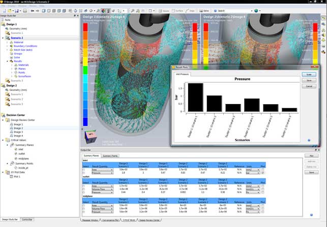
The new Decision Centre feature provides users with an environment for the assimilation and comparison of results from multiple scenarios, using summary tables, graphs and plots
The 2010 release brings a host of tools for those looking to make the most of their time when simulating fluid flow and heat transfer. Perhaps the biggest shift for this release is the ability to conduct multiple design studies within the same interface and within the same dataset. While previous releases have facilitated multiple design studies, this release brings this to the fore and gets rid of the workarounds. This is done on two levels, both when setting up those studies, and then when providing the tools to visual and interrogate the multiple results sets.
Multiple studies
Everything that pertains to a design project can be stored in a single dataset and this means multiple studies can be carried out within the same working environment.
To define a study the first stage is to set up the geometry. CFdesign has always had rock solid connections to the majority of CAD systems, either through native data transfer or through standard/proprietary formats (such as ACIS or Parasolid). Once the geometry transfer is complete, the details required for CFD need to be added.
For an internal flow problem (such as a valve or pump) the inlets and outlets need to be capped off, which is a trivial matter within CFdesign. For an external flow or a product simulation, which has both internal and external flow or transfer, then the volume within which it operates needs to be defined.
CFdesign 2010 has new direct modelling type techniques for quick, efficient modelling of external volumes. Geometry can be pushed and pulled into shape, and basic primitives are used to build up the required form. Incidentally, the same tools are used to create regions for mesh refinement later on in the process, allowing users to zero in on areas where more accurate results are required.
Dynamic input has been increased across the board, with the system feeling much more interactive when working work with the model, rather than pulldowns and dialogs.
The next stage is to define the inputs and outputs, fluid regions, heat sources and then the simulation can be run. This is pretty much unchanged from the previous releases in terms of workflow, but has become much more interactive, focussing on the model and context sensitivity input.
The dramatic change for 2010 is that much of the work from the first study can be re-used to carry out further investigations. Reusing a project is pretty simple. Assuming that the same geometry is to be used, the project is simply cloned. This creates a copy of the original and another branch in the simulation tree - or as it’s known, the Design Study Bar. From here the inputs can be adapted as required and the analysis re-run.
If different geometry is required, perhaps swapping potential design variants or family members, then users have full control over individual parts and sub-assemblies as well as part suppression tools.
Results interpretation
Once one or more results sets have been created, and assuming the results are accurate, the important stage of the process begins, that of results interpretation. The Decision Centre provides a centralised set of tools for inspecting multiple results sets. Up to four datasets can be loaded up at one time and these can be displayed in a very organised manner. Views are synchronised, so it’s possible to dive into each and find weak points, inspect areas of concern, and have the display in other datasets maintain the same view.

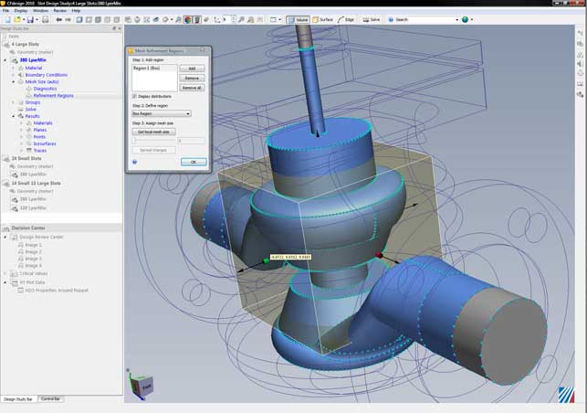
CFdesign 2010 features a set of direct modelling tools that allow you to create external flow volumes using primitives quickly and easily
The results data is presented in a tabular manner, so multiple sets of data can be filtered down to find those of most interest, and those which need further investigation, without any impediment. Charting and graphing tools are also supported in this environment. While the fancy 3D fringe plots are fine for getting an understanding, it’s these more traditional types of output that will be used as the basis for design decisions.
Alongside this, there is the full array of result visualisation tools that CFdesign has had for some time, for vector plots, flow animation, and iso-plane creation. These too have been enhanced. For example, textures can now be placed on components to help add context, the existing cut-planes can be formalised in the Study Bar, so they can be used across multiple studies when projects are cloned (rather than having to create them individually). Finally, a reference value can be added when plotting charts, whether that’s a performance metric, or a pass/fail benchmark. At present results can’t be colour coded on the basis of that reference but it’s usable all the same.
The importance of CFD
Simulation is a rapidly advancing field with many active vendors. Some are more traditional, providing the higher-end, PhD driven systems of old, while others are pushing simulation and analysis into the mainstream, providing tools that designers and engineers can dig their teeth into. Of course, whichever system is used, having a solid understanding of the principles behind these systems and physics they describe, is key to getting good results.
The main advantage of any simulation tool is to prove out a design variant before it moves to physical prototype or manufacture. But doing a single simulation doesn’t give you much - it just gives you a binary answer (yes or no/ pass or fail). To make full use of these tools, you need to be able to explore a design, to play with values, variables and inputs and see what the optimum solution is within the defined constraints.
Conclusion
This release of CFdesign is impressive. Having watched the application grow over the last ten years, it’s rapidly gained a position as one of the leading examples of truly designer-led CFD. CFdesign 2010 is not about flashy new functionality, it’s about taking the existing tools and making the most of that functionality.

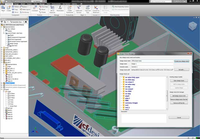
The Design Study Manager allows users to quickly and easily create and manage multiple designs and scenarios from any MCAD environment, such as Inventor
From the tools that manage the movement of data from your workhorse 3D CAD system to CFdesign, through the revamped working environment (which is rather elegant in its simplicity) and then onto the new Decision Centre’s visualisation and reporting tools, this release is all about enabling the user to make real and high-impact design and engineering decisions, based on digital experimentation, and not just a cursory peep in a product’s performance.
The ability to visualise and inspect multiple data sets in a single window, without having to load multiple files, or manage multiple graphics displays, sounds like a small thing, but the power it gives you to see trends, finds weak spots, tweak performance, is incredibly compelling. All in all, it’s a good release and I can’t wait to see what the team comes up with next.