Tracking the updates (which are every month or so) is something that takes time and patience.
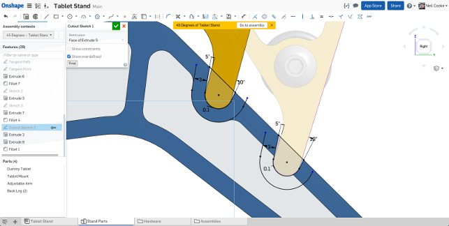
Onshape’s new in-context design tools give you more freedom when working with moving assemblies and building references from multi positional data
Unlike other traditional systems with a quarterly or annual update, each month brings a mix of brand new functionality and an extension to existing tools. While some months will see more of the latter, the last quarter’s worth of updates have included some pretty wholesale additions to the system and it’s worth exploring these in some depth.
So let’s do that and start with the two big ticket items. Sheet metal is second, but let’s begin with in-context assembly design.
In-context assembly design
The biggest news out of Onshape in recent months looks to address one of the key missing capabilities in the system — the ability to make edits to parts in the context of an assembly.
Until recently, Onshape separated its assembly design (in Assembly Studios) and its part geometry design (into Part Studios).
For simple cases, this made sense. Design the parts using a multi-body approach to create geometry, both from scratch and using references from other geometry. But for those that work on dynamic assemblies, where parts move and interact, this nobbled their ability to have parts in multiple positions and pull references to build further features.
Those that have done this kind of work in traditional CAD systems will know that the process is one fraught with complexity, particularly considering how file based CAD systems work — so let’s explore that briefly before we look at how Onshape is handling it.
In-context assembly editing is useful for many reasons and traditional CAD systems do a pretty good job of it — but with some limitations. Most allow you to have a set of geometric parts, experiment with mates and assembly constraints and test the mechanism.
However, ultimately, they only store the position or state of those parts at the last rebuild of that assembly (typically when it is saved to disk) — and it’s this last part that’s key.
To build an in-context feature, the system allows you to add geometric features, perhaps reference existing geometry mixed with new, that affects multiple parts. That’s in-context assembly design. If your parts don’t move after this (in terms of the CAD model), you’re golden.
But what if you want to shift the assembly to build another feature? This is where the shit hits the fan. If you then move the assembly (and this is typically not something held in the history tree), the system is still trying to rebuild those features based on previous references, but applying it to the new assembly position. If the edit is minor, it might work, if it’s not, it’ll typically fail.
Onshape side steps this issue by adding in one, deceptively simple, set of references. In addition to geometry and position, it also adds in time.
Onshape’s infrastructure is built on the idea that everything is recorded and available. Not just a simple list of features that makes up the geometry of a part, but everything that’s done to that geometry over the course of its development. It’s key that we’re clear on this.
A traditional history tree is a list of operations that are needed to get to the fi nal part. They typically don’t record any edits to individual features as you work on your mode. They simply store the parameters for each of those features, in a logical order, at the point of the last save.
That’s not a true history, it is a recipe to rebuild that part to its current state.Onshape’s history differs. Aside from view manipulation, the system stores everything that’s done to your model — from beginning to end, from geometry creation and edit, to positional information in assemblies. As a result, it not only knows the latest state of the model but also has a full history of everything you’ve done to it.
That simple fact makes it able to do some very interesting things when it comes to in-context assembly design.
Essentially, Onshape knows all of the relationships in a part’s development or movement at the same time, rather than relying on a replay of a set of fixed operations. You can use that to build parts more effi ciently, rather than trying to fi ght against the regeneration of a set of geometry.
You can move components in an assembly, build features from references, move the assembly again and build more.
The system handles tracking those various states for you and they’re fl agged up in the history and feature list. If at any point, you want to make edits, you open that “in-context” edit and make your changes and the system handles everything downstream.
It’ll take those with a background in traditional 3D CAD systems a little while to get their heads around this (it certainly did for me), but once you realise what’s going on, it makes huge sense and is remarkably powerful.
Sheet metal design
One of the big updates in recent months is the addition of sheet metal design tools.
If you’re currently engaged in sheet metal design with 3D CAD, then you’ll already know the basics. If you’re not, the concept is that you start with a uniform sheet and then build up the forms you require, maintain the thickness of the sheet and incorporate the manufacturing and fabrication requirements of sheet metal and press brakes (in terms of bend radii, k-factors and such).
In the 3D world, this is typically combined with the ability to unfold that folded form to create your blank form for preliminary manufacture.
Most sheet metal design tools built into mainstream 3D design systems have these tools and many more, usually with the model being available either in the folded or unfolded/flattened form. Folded for design, flattened for documentation.
The same is true of SolidWorks, as it is for Inventor, Solid Edge or Catia and NX. So how has Onshape spun its version of sheet metal design?
Let’s be clear from the outset, the sheet metal tools in Onshape are formative to say the least — the feature set isn’t particularly rich at the moment, but what you can gain is an understanding of where things are heading.
The first thing to realise is that there’s no question of having multiple states for sheet metal parts — Onshape maintains both the folded and the unfolded forms at the same time. Edit the 3D model and it’s instantly reflected in the unfolded form.
Alongside this, Onshape also maintains a more tabular set of data that gives you a list of bends and rips in your parts which can assist with documentation, particularly for passing down to fabrication.
This enables a couple of interesting workflows. If you’re starting from scratch, with a single face, then adding in your bends, flanges and other features, you get immediate feedback in the secondary window on how your blank is coming together.
If, on the other hand, you’re starting with a solid 3D model, then looking to convert it to sheet metal, you have some very interesting tools. Anyone that’s worked this way knows that the process of ‘ripping’ a 3D model into sheets is an iterative process.
You begin with identifying your base sheet, define all of the bend and material parameters, then work around the model’s faces choosing whether to rip an edge or to bend it. In traditional systems, you’re constantly flipping between the folded and unfolded state to see how the blank is, looking for any areas where your decision is causing design for fabrication issues (such as fl anges that don’t fit into the form).
With Onshape’s approach, you’ve got both running in parallel. As you can see from the image above, there’s a set of separate sheets (representing each face of your design) and your task is to join these up into a single blank.
Having both views makes the process much more intuitive and enables a lot more experimentation to see the results in both the folded and unfolded form, simultaneously.
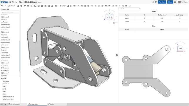
Onshape’s new sheet metal tools give you some interesting ways to solve that age old “how do I unfold this?” problem with live feedback on both the 3D model and the resultant flattened blank
Modelling updates
While we’ve talked about two biggies in the geometry creation realm, the last few months have also seen some small, but equally key updates to existing tools as well as new additions.
A good example is the ability to create bridging curves. This allows you to quickly define a curve that connects two entities together — whether to assist with the creation of a subsequent feature or to add more control over form.
While these don’t yet have curvature continuity (like a blend curve in Alias or Rhino), the option to add in tangency as well as pure positional, is good enough to help create more complex forms — particularly when you’re dealing with transitions between two sets of geometry.
Drawings
Recent months have seen the drawings capabilities of Onshape progress nicely.
There’s now a lot more control over how you position those all important views, as well as the ability to add in those less often used, but all important details and annotations.
A good example is the ability to detach views from their parent, something that’s essential for a cleanly laid out drawing, whether that’s sections, details or isometrics. Another recent addition is the ability to ‘break’ a view.
This is ideal for those looking to detail parts that don’t readily fit onto a drawing sheet, but want to retain accurate dimensioning (I’m thinking shafts and other ‘wide’ products).
Other updates include the ability to add in sharps (intersection points for fillets and chamfers), automate the creation of callouts from threaded holes (and Onshape’s hole creation tools are standard’s based and super slick, something other vendors could take note of). And while it might seem a small update, the ability to have annotation operations persistent (remains live once complete), will make crunching through those annotations much more efficient.
Finally for drawings and documentation, while we discuss the integration with OpenBOM elsewhere in this issue, the combination of OpenBOM and Onshape, both being cloud-based services, gives you a lot more control over how those key BOMs appear on your drawings over and above the built in tools.
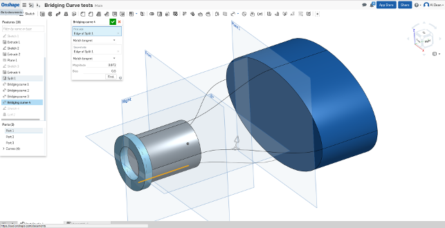
The existing tools are gaining more richness of functionality — such as the ability to build bridging curves, which respect tangency, between existing geometry — perfect for more complex and controlled loft operations
Conclusion
If there’s a theme to this set of updates (over the period of three months), it’s that Onshape is exploring the potential for its different way of working and cloud-based infrastructure to good effect.
As you might expect, there’s a good deal of enhancing the existing functions so that they work how you would expect from more mature systems (see; greater flexibility in terms of feature creation control) as well as adding a richer set of tools.
Then there’s a rich seam of taking advantage of those infrastructure (eschuing the file-based system for a more comprehensive complete history of model construction) to break new ground.
The sheet metal tools show the parallel computation of the cloud to great effect — allowing you to have both the folded and unfolded forms available during design to make the process more efficient and intuitive.
Then there’s the work done to enable in-context editing of assemblies, which takes a dramatically different approach to other systems on the market — and brings a fascinatingly innovative set of tools to the fore.
Onshape’s relatively young years are still showing in some areas, but the richness that’s essential to getting more complex tasks complete is growing and growing in new and interesting ways.
Onshape App Store: New additions for FEA & PCB interop
Last year, Onshape launched its App Store for third parties looking to build offerings for the user community.
These varied from more simple connections to existing desktop products (that allowed loading of Onshape data from the cloud to a local application), through connection between two cloud-based services and finally, the providers looking to build applications directly inside Onshape’s user interface and data storage infrastructure.
The last couple of months have seen a couple of interesting additions to this portfolio, both of which provide fully integrated services for those looking to expand Onshape’s capability.
Let’s take a look at two of those — covering Finite Element Analysis (FEA) and PCB interaction.
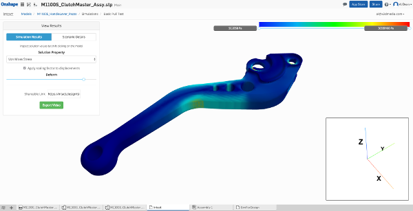
The first is Intact from Intact Solutions. This is a pretty simple FEA-focussed tool that allows you to conduct a number of simulation types on your Onshape geometry.
It has a simple, clean interface, offering a combination of pre-baked, template driven simulation studies (with sensible names, such as squeeze, squash, twist etc.) which predefine much of the work. You can also dig into the more advanced settings and set-up each study as you require, selecting faces, applying loads, restraints and materials as you go.
Results are computed on the cloud and you get your notification that the job is complete.
Post processing and results inspect tools are basic, but will give you a quick idea of where any potential strength related issues lie (see image above).
The second is the not-so-snappily named “IDF to 3D PCB” from Simplified Solution.
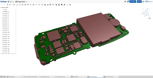
As you might expect, this allows you to import PCB data from a variety of sources in the usual two file (board + component) formats (from the likes of Altium, Cadence and Eagle), use a set of tools to manage which components you want represented in your 3D model, swap out any fuller representations (IDF files typically just store prismatic component dimensions) and build a 3D model, around which package work can take place.
The result is an Onshape assembly studio with your parts in place and ready for further work.
| Product | Onshape |
|---|---|
| Company name | Onshape |
| Price | $100 per month |