Solid Edge ST10 – In the world of mainstream 3D design and engineering systems, Solid Edge has been a consistent player for over two decades. We take a look at the latest version that brings some of Siemens’ brand new technology to bear
Solid Edge has been on the market for over two decades now. Since the acquisition by Siemens, it has been through something of a renaissance in interest, particularly with the introduction of Synchronous Technology back in 2008. This brought non-history based modelling techniques to the system alongside its more traditional capabilities.

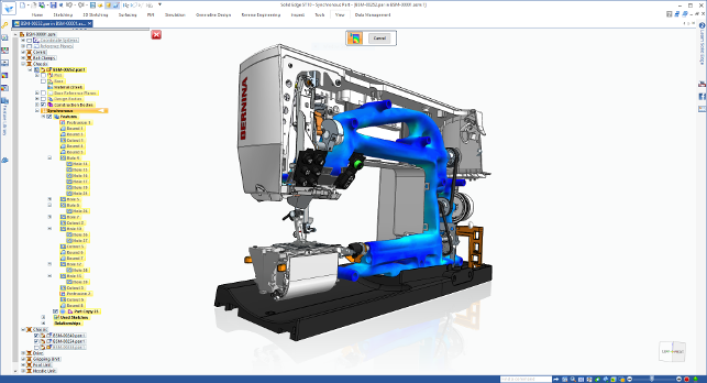
Solid Edge ST10 gets Siemens’ convergent modelling tools as well as Frustum’s topology optimisation engine
This year’s major release sees this work continue, but the big news is going to be the introduction of a couple of pieces of technology from the wider Siemens PLM group (and some third parties) that adds brand new capabilities to the system. So let’s dive in.
Solid Edge ST10 – convergent modelling
The biggest news for Solid Edge ST10 has to be the integration of Siemens’ convergent modelling technology (which first debuted in NX in the last release).
For those that aren’t up to speed, this is building on the ability to work with a mix of both solid and surface modelling tools and adds in the ability to work with meshbased data.
In the context of Solid Edge, this has some interesting workflows. If you’re importing geometry from another source, be that a laser scan, a downloaded or supplier model, you can import it and carry out some functions with it. Where convergent modelling gets interesting is when you need to start to combine these forms with more traditional forms of CAD.
Yet, because the two can co-exist in the system, it’s possible to use this data as reference material for modelling around, but when it comes to carrying out additional operations, then you need to understand the limitations.
Convergent modelling allows you to carry out operations, for example, placing a hole through a part, adding additional features, to any mesh-based part.
As soon as you do, the system converts everything to a mesh-based form. While the features remain editable (they’re shown in the history/feature tree), the end of that history list is a mesh form and influences what you can do next.
Reverse engineering
Another area that’s worth addressing is the simple fact that mesh-based isn’t always perfect.
If it has been exported from another CAD system, chances are it’s watertight. If not, and if it’s from a laser scan, then chances are that you’ll have areas to clean up, repair and patch.
To assist with this Siemens has built in a pretty well developed set of reverse engineering tools that you can dive into to edit and repair portions of your mesh.
Whether that’s to remove artefacts from your mesh, or to patch up areas that aren’t needed, the tools are there.
Once you have your model in a fit state to continue with, there are then tools to fit more traditional geometry to the mesh. Whether that’s primitive faces (planes, cylinders etc.) or something more advanced, these tools allow you to find ‘regions’ in your mesh (based on curvature changes) then add in the geometry you need.
If you’ve worked with other reverse engineering systems (such as Geomagic or RapidForm, or indeed, Delcam’s PowerShape), you’ll be familiar with the type of thing that can be accomplished.
While this isn’t a wholesale meshbased modelling system, its certainly comprehensive enough to allow you to work with the data you have. For those working with laser scanned data in particular, it’ll let you repair and clean up your mesh so it’s useful, then add in the features you need to progress things further.
On top of this, don’t forget, you’ve got the surface modelling tools that Solid Edge has had for many years.
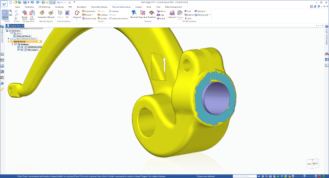
Solid Edge ST10 brings a range of reverse engineering tools for working with mesh-based data
Solid Edge ST10 – topology optimisation
Those that follow what Siemens PLM does in both Solid Edge and NX will know that in the last release of NX, the company integrated a set of topology optimisation technology from Frustum, which alongside the introduction of convergent technology, made for a very interesting set of tools, primarily aimed at the additive manufacturing world.
The good news is that the same technology and workflow has now been integrated into Solid Edge. So let’s step through what they bring – there is a visual below but the devil, as we all know, is in the details.
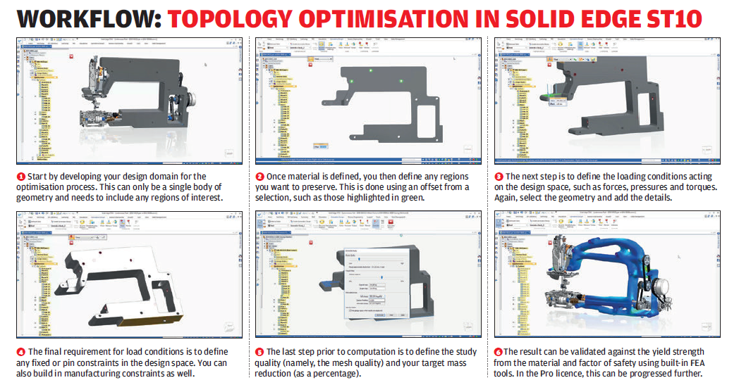
The topology optimisation process is found under the Generative Design tab (we won’t go into why that’s a bad name here). Your starting point is a single body of geometry.
This should describe your design space/domain and any features you want to retain.
The next step is to define the material to give an accurate estimate of mass saving when it’s all done and used in validation of the results against yield strength and a factor of safety.
You then work through defining your boundary conditions for the study.
This involves defining any keep out regions or ‘preserve regions’ that you don’t want touched, loads (such as forces, pressures and torques) and constraints (either pinned or fixed).
At this point you can also define the manufacturing settings. These allow you to guide the result to avoid any internal voids or any overhangs (in a specified direction) — both of which are useful if you’re either machining or additively manufacturing the end result.
Once all these are set up, you need to defi ne the optimisation parameters. Topology optimisation is all about mass reduction. You define the ‘quality’ of the solution, which essentially controls the mesh element size (more elements mean a smoother result but a longer compute time) and a mass target.
This can either be a hard mass value or a percentage. Most will probably go for the percentage value. Where the Target value is useful is if you’re using an existing component as your design space or have specifi c requirements you need to reach. You can also add in a factor of safety, which will be used in validation of the results.
Handily, the system also gives you an estimate for the computation time. Note, this is a pretty compute heavy process and you could, particularly with the instance shown here, be talking about hours.
Once the compute is complete, you’re shown a stress plot that will map your loading conditions to the resultant form to give you an idea of how the new form works.
In terms of what you can do next, you’ve got a couple of options. Of course, these are inextricably linked to the convergent modelling tools as the result is a mesh-based form. That means you can start to build up or rebuild engineering features where needed (though bear in mind that if you do, you won’t get hard surfaces — they’ll become a mesh as you merge them).
As you’d expect, this type of tool is ideal for experimentation and you’re able to run multiple studies, rerun optimisation studies after design changes and generally see where you can get to.
Finally, if you’re looking to take these forms to manufacture, you can export them to STL or the newly added .3MF format.
At this point, it’s worth discussing the pricing of the generative design tools introduced into Solid Edge ST10.
There are basic tools included in all levels of Solid Edge. That’s Classic and Premium — not, however, the 2D, drawing only entry level bundle. That said, there’s some heavy limitations on what you can do both during the optimisation process and with the end result.
Essentially, you can load and constrain a design space (using basic forces and constraints) and view the results. That’s it.
If you are looking to use the more advanced loading conditions (including torques and pressures and pinned constraints), manufacturing controls, conduct a stress-based validation (and view the results) and export the results (either directly to STL or back into Solid Edge for further work) and duplicate your studies, then you’re looking at a Generative Design Pro add-on, which isn’t going to be cheap.
To enlarge image click here
Solid Edge ST10 – 3D printing & additive manufacturing
With the addition of the topology optimisation tools and convergent modelling tools in Solid Edge ST10, it’s clear that Siemens has its mind on the Additive Manufacturing world. Interestingly, it has also done some work at the opposite end of the spectrum to greater support desktop-level 3D printing.
The STL export options have been expanded — both in terms of format support (it now adds 3MF format for richer 3D print communications) as well as some tools to assist in previewing your part (or group of parts) on a build platform. You can then export the data (most likely) or connect to a third party to order the parts.
Siemens has integrated with a German outfit called 3yourmind to build its 3D print brokerage service into Solid Edge. This means you’ll get a quick preview of the part, an indication of ‘printability’, a list of possible materials and a good idea of cost.
3yourmind’s service gives you a good set of filters for not only build technology and material, but also location.
Most of us have existing relationships with suppliers that we favour, but if you’re looking for more exotic materials or looking to explore other options, it’s a good starting place.
Solid Edge ST10 – updates to synchronous technology
While there’s been a slew of updates across the board for this release, you might be forgiven for thinking that there’s not been much work done on the synchronous technology front.
Although it hasn’t been the focus for the Solid Edge ST10 release (the toolset is mature already), this isn’t to say that it hasn’t been addressed.
Perhaps the most useful, particularly for those working on complex assembly models with a lot of repetitive fasteners or sub assemblies, are the new tools to help clone assembly mating conditions. Whereas in previous versions it was possible to pattern components based on the locations of other components (e.g. a cap for every bolt head), this has been extended to pattern based on feature recognition (e.g. a retaining clip assembly for every mounting location), but what’s cool is that while this is feature-driven patterning, there’s no need for an actual feature, it uses geometry recognition.
Data management & collaboration
To round things out, let’s talk about the last two updates that we’re looking at for this release, starting with data management.
Those that are familiar with Solid Edge’s development will know that, some time ago, the default data management solution was built on Microsoft SharePoint.
This changed in the last release (ST9) with Siemens introducing a set of tools that enhanced the indexing tools native to Microsoft Windows to add in some CAD flavoured knowledge.
The result was a basic data management system that worked, out of the box, without any special server requirements and was just as applicable to the smaller workgroup using a network drive arrangement as it was to the sole trader just working with their file system.
This continues for this release with extra sophistication added to those tools focussed around enabling teams to ensure that they’re both working on the same, up to date data, as well as managing file duplicates across projects (which has the benefit of reducing repetitive work and potential inventory) using a new Design Manager utility.
While the built-in data management tools are the entry-level in the Solid Edge range, there’s also a good level of integration with Siemens’ Teamcenter PLM system. This release sees the ActiveWorkspace technology from Teamcenter integrated into SolidEdge, which offers a pretty slick gateway into the PLM world.
Now, on to the collaboration aspects over and above data management and sharing in a workgroup. Starting later this year, Siemens will be beta testing a new Solid Edge Portal. This will allow users to upload files for sharing with partners in a secure environment.
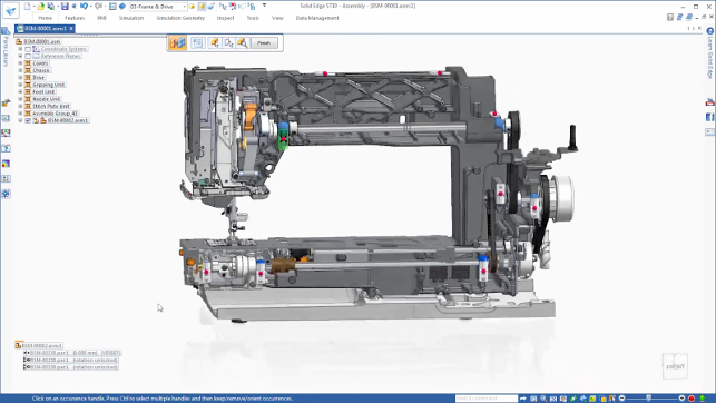
While not a core focus for this release, synchronous technology sees a few updates, particularly in the area of assembly automation and rapid insertion of multiple sub-assemblies
In conclusion
Solid Edge ST10 looks like a comprehensive release across the spectrum of the system.
The introduction of convergent modelling and the associated reverse engineering tools are going to make life easier for folks working with imported mesh geometry or perhaps, more commonly, data from laser scan systems.
For instance, whether that’s capturing physical models for progression into design and engineering or for capturing existing forms for interfacing (think: aftermarket products).
Alongside this, you’ve got a bunch of tools that bring some sophistication to the 3D print or additive manufacturing workflow.
On the subject of generative design, I think we need to address two things. Firstly, Siemens is calling this generative design. But it clearly isn’t — it’s topology optimisation, pure and simple.
The second matter to address is the price. Siemens won’t confirm the price for the add-on, but having seen ball park fi gures, it’s going to be expensive and that’s on top of your existing licence or subscription.
Yes, there’s some value in the freemium tools, but the ‘pro’ tools are based on early stage technology (Frustum’s own cloud-based service is only just on its fi rst, 1.0, release cycle).
To make use of this type of technology, users need to experiment and to be able to take it into production and find the value for their own products. Hiking up the price for the ability to do that isn’t going to help aid adoption.
Elsewhere, some good work has been done on other aspects of the core of the system.
The shift to make the operating system more useful as a data management tool is a good one, particularly to help those that don’t see the need for such a tool (as it ‘just works’). The updates to synchronous technology will also help out where you need it.
Then you get to items like the new CFD focussed add-ons and the changes made to Solid Edge CAM (Formerly CAM Express) both of which are additional cost options.
It’s interesting to see how Siemens’ mainstream team planning and executing of Solid Edge’s development are starting to take advantage of the wealth of technology available in Siemens’ arsenal.
Yes, they’re going to add to your investment, but these are productive tools that will benefit you if you have the need for them.
All in all, it’s a good update to an already mature and comprehensive system. As you might guess, it looks like the development of synchronous technology has started to slow down as its reaches a level of maturity — the good news is that Siemens is exploring new avenues while continuing to refine existing tools.
Add-ons for Solid Edge:CAM, CFD and technical pubs
Alongside the core tools updated and added in this release, there’s been some work done on the inhouse add-ons for Solid Edge.
While the Solid Edge bundling is pretty simple, these add more specialist tools if you need them. As ever, they’re either integrated into the same interface or they work alongside it, with good data connectivity.
Solid Edge CAM
First introduced back in the early 00s, Solid Edge CAM (formerly known as CAM Express) is a side seat of Siemens’ enterprise level NX with many of the advanced tools stripped out, but retaining the machining capabilities for which the system is known.
Things haven’t changed a great deal for this release apart from some new tools that allow you to quickly repurpose geometry from Solid Edge for machining — whether that’s building jigs and fixtures or adding machining stock.
There’s also the integration of Siemens’ own take on adaptive roughing, which adapts your cutting operation to increase tool life while enabling the cutter to use a large portion of the flute length.
There’s also access to a web-based post processor hub.
Solid Edge flow simulation
Introduced a couple of years ago, FloEFD was a Mentor Graphics developed third party add-on for Solid Edge to add Computational Fluid Dynamics (CFD) simulation tools directly into the Solid Edge interface.
In the intervening time, Siemens has acquired Mentor so the FloEFD application is now an official part of the product offering.
As you’d expect, it gives you a designer/engineer-focussed fluid flow and heat transfer simulation capability. So whether you’re concerned with heat or flow, you’ve got a good set of tools available to do just that.
And because of the systems maturity (it’s based on Flomerics’ tools which have been around for a decade or more), it’s well developed, capable and pretty well thought out.
Solid Edge technical pubs
For this release, there’s been work done with QuadriSpace to enhance the technical illustration and publication tools that are sold alongside Solid Edge.
These have been rebranded as Solid Edge Illustrations and Solid Edge 3D Publishing.
The difference is that the first is the entry-level and gives you the means to develop technical illustrations, with a set of tools to repurpose your CAD geometry and then adds in those all important annotations and other elements.
Solid Edge 3D Publishing, on the other hand, is aimed at those looking to develop live work instructions as well as other technical publications and gives you a whole host of tools to create staged assembly, disassembly and service instructions.
| Product | Solid Edge ST10 |
|---|---|
| Company name | Siemens PLM |
| Price | See text |