
Femap has always been one of the leading examples of pre/post processor software for simulation and is now a strategic part of the Siemens offering. It not only provides the front end to Nastran-backed analysis within the Velocity Series but is also going great guns within the worlds of NX and analysis.
At the front end of the process, Femap offers a means to take raw 3D CAD geometry and repurpose it for simulation. By repurpose, I’m referring to those routine tasks such as fixing geometry, abstraction (removing non-critical features), mesh creation and refinement as well as boundary condition assignment, that deliver a simulation that will both run efficiently and give accurate results. Femap then communicates that to the solver, which is typically Siemens’s NX Nastran, but can also be other Nastran variants, alternative commercial solvers, and in house codes using the API.

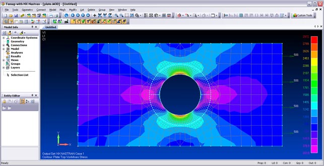
By adding a washer to this hole, stress concentration is relieved around it and the results are much more accurate
Once the simulation is complete, it then provides you with an environment for inspecting, interrogating and visualising those results to extract meaningful information on which design and engineering decisions can be made.
The core concentration for this Femap release is the addition of a number of tools to assist with the core pre-processing stages of geometry clean up, mesh creation and mesh refinement. In a typical workflow this starts with raw geometry from a CAD system.
Femap reads the majority of data formats, including all the usual suspects – IGES, STEP, VDA/FS – but also proprietary kernel files, such as Parasolid and ACIS, and native data formats, including NX and I-deas (as you’d expect), but also Pro/Engineer and SolidWorks. The SolidWorks data translation tools have been updated with this release, with the added ability to read Parasolid data straight from SolidWorks parts and assemblies.
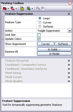
The geometry and mesh refinement and adjustment tools have been consolidated into a single, simple dialog
Once the data is in the system, the next step is to clean it up for simulation purposes and this is something that’s seen a big focus of effort for this release. In the first instance, Femap now features a new mesher that calculates the meshes based on global 3D space, rather than individual face geometry. This means that while traditional meshing tools use each face as a controller for the mesh creation (which gives rise to problems when trying to squeeze elements into tiny sliver faces), the new mesher ignores faces and uses a global mesh control that works over and above the individual geometric elements. The end result is that, for many cases, higher quality meshes can be achieved on the first pass.
Fixing geometry
Ideal geometry is not that common and as a result, Femap has always been good at diving in and fixing problems. The new Meshing Toolbox is a deceptively simple dialog that both consolidates existing geometry clean-up and meshing tools, as well as introducing some new technology. The first, and arguably the most essential, of these tools is the Entity Locator. This enables users to quickly find errant geometry problems – such as short, non-manifold and free edges, and sliver faces – and then combine surfaces and edges to amalgamate slivers into larger areas of geometry.
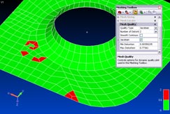
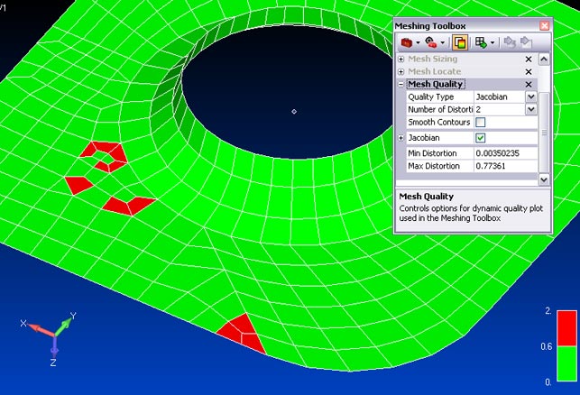
Live Quality Display checks colour codes each element (for aspect ratio, internal angle, warp, taper and Jacobian checks) and the display updates in real-time
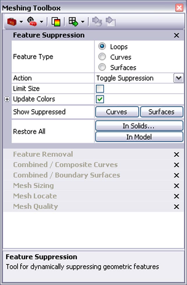
While these tools are used to adapt small areas of problematic geometry, there is often a requirement to remove details (such as holes or fillets) which aren’t critical to the simulation process. This is commonly referred to as de-featuring or abstraction. There are two new commands which relate to this: feature removal and feature suppression. Feature suppression ignores the superfluous features and meshes over them, without altering the underlying geometry. Feature Removal, on the other hand, removes and patches over feature geometry permanently.
Adapting meshes
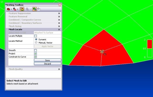
There will always be areas in a mesh where elements need to be added or removed and the new mesh sizing tools do this interactively and dynamically. As element size is typically controlled by the number of nodes placed on an edge, adding more will increase concentration, whilst removing them will make the mesh sparser. In Femap, this is done by clicking edges to add or remove nodes and the mesh updates in real time. If changes are required on individual elements, the user can dive in and move individual nodes, either in free space or by sliding them on the underlying surface model. Version 10 now features live quality checks which colour code each element according to user-defined values (for aspect ratio, internal angle, warp, taper and Jacobian checks) and the display updates in real-time. Interestingly, for those working with Nastran, these checks have been adapted to match the NX Nastran mesh checks, so both systems sing from the same hymn sheet in terms of quality.
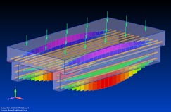
Femap now has a set of tools to connect and join up distinct element types to create a usable model
Mixing up mesh types
Another core focus for Femap 10 is greater support for mixing all manner of element types. While there’s a temptation to mesh everything these days just because modern workstations are so powerful, there are a few tricks that experts have been using for many years to make solve times more efficient. By mixing standard tetrahedral elements with beam, shell and mid-surface elements, an FEA model can be created that not only solves quicker but with the same accurate results. The trouble is that creating these forms is problematic, particularly where element types meet, such as where a mid-plane model meets a standard model. Femap now has a set of tools to connect and join up these distinct types to create one usable model. This is supplemented with new tools to assist with generating a mid-surface from a constant wall thickness model.
Visualisation
The big news for Femap 10 is the ability to transform the results display, which makes it easier to switch between different co-ordinate systems. This gives the ability to match the results display to the load or operating condition under simulation, in a very explicit manner. The system already includes a huge raft of result visualisation methods and filters and this backs these up.
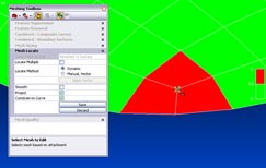
The Mesh Editing tools allow users to dive in and position individual nodes, either in free space or sliding on the underlying surface geometry
Conclusion
Femap is one of those systems I love looking at. You take it all in and are left with very few questions. After many years of development (by a surprisingly small team), the system represents a very well evolved set of tools for handling common FEA-related pre- and post-processing. When it comes to handling problematic geometry and meshes, this latest release takes ten years’ worth of development, consolidates it into a deceptively simple dialog and enhances it with tools to make the tasks easier and more intuitive.
In terms of meshing , the automated tools can be used to get so far, where manual tools take over to refine and create the perfect mesh that will result in efficient solving and accurate results. And this is in addition to all the result visualisation tools that have been there for a good long while.
Those within the Siemens PLM Solutions user community are most probably aware of Femap, considering its place in the Velocity Series offering, but outside of that, there’s still huge potential. Whether teamed with NX Nastran or another solver code, this system provides a ‘Swiss Army knife’- like set of functionality that allows users to get the best out of simulation in the most sensible manner – ensuring that the highest quality data for its purpose can be worked with quickly and efficiently.
Geometry splitters
Where holes (and other features where stress raisers occur) need to be retained, the new geometry splitters allow subdivision of surface geometry using a number of different methods. A basic split can be created simply by selecting two points on edges to split it between. Geometry in surrounding surfaces can also be referenced, such as edges from which to continue tangency. The other two tools allow tangency from one edge to a point or between two edges to be maintained.
In addition to the splitting tools are two intriguing little commands: washer and pad. These automate tasks commonly carried out by an analyst to refine the mesh around specific features. There are explicit commands for each and they make very light work of these tasks –simply select the geometry to work around, then add options (for example, for the washer, whether to split the washer or not) and away you go.
At a glance: FEMAP 10
More robust first pass meshing using 3D space, rather than geometry boundaries
Consolidated and enhanced geometry error finding and clean up tools
New interactive mesh refinement tools
Dynamic, real time mesh quality checks
Improved parity between Femap and Nastran set-up
Ability to translate or transform results visualisation co-ordinate system
Improved support for building mixed element meshes
| Product | Femap 10 |
|---|---|
| Company name | Siemens PLM software |
| Price | On application |


