
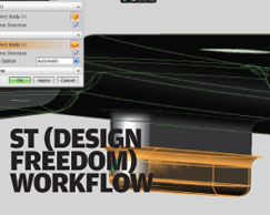
When stripped back to the bare basics Synchronous Technology is all about allowing you to work with geometry in a history free model that retains feature information and allows you to work with your part’s form on the fly – with no recalculation required. On top of this, you have the ability to define relationships between geometric features, dimensions and other parameters without having to have the expert knowledge of how a part or assembly has been constructed. The first thing to note is that within the context of NX, Synchronous Technology is being implemented as Design Freedom, confusing I know, but the thought behind it does stack up as in comparison to Solid Edge the way the technology has been built into NX differs greatly, so let’s explore that.

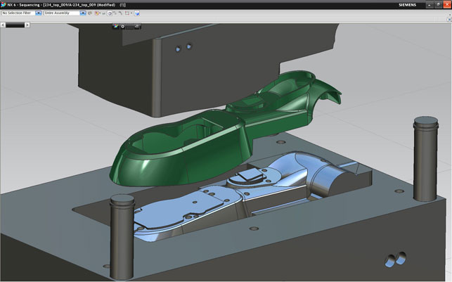
There’s been a huge amount of work done adding intelligence to the NX mould design tools. Mould cavities are now linked back to CAD data, meaning design changes can be propagated to mould quickly and automatically. If you’re working with multi-cavity moulds, there are tools to reduce the upfront work, so that mould cavities are laid out with sketches, then the actual part geometry swapped out when needed.
ST in NX basics
ST in the NX environment doesn’t split your working practices. The last few releases (NX 5 in particular) have seen more and more direct editing tools built into NX, with the system more capable of consuming this new technology and making it usable with the existing tools. Essentially, the difference is that you can flip between History and History-free mode on the fly, within a part, done so you can either keep a trail of everything in serial sequence or not without changing the actual work done. What’s key is that you have a much more dynamic way of creating, editing and interacting with geometry. This last point is something that’s also seen a huge ongoing focus for NX – user interaction: so let’s look at where the system is at for this release.
Geometry is directly manipulated and features recognised, such as holes, blends, chamfers, and shelling. The point is that these features (with the exception of shells) are not stored in a traditional feature History tree. As you edit, the system uses a new tool called Active Selection to find common geometry, meaning edits to multiple features can be made in a single operation.
This allows for the editing of features such as holes en masse, but with some intelligence, so that only features within your field of work are edited, rather than making a change and finding you’ve edited a small hole on the other side of a large part by accident.
One thing that does appear in the feature tree is a shell. This enables you to maintain wall thickness when working with the ST-based editing tools, allowing you to take additional geometry, paste it into your part, then use the shell face to create and maintain the uniform thickness – your selection is the face that is integral to the part.
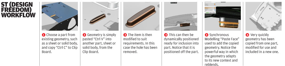
This cutting and pasting of geometry is something that’s highly impressive and is referred to as ‘scrapbook modelling’. Whereas in other systems you might be able to use basic forms of cut/copy/paste, the flexibility and lack of dependence on history with ST makes this really usable. Geometric features can be cut and pasted within parts or between parts, so features that need to match, where interfaces lie, can be created very quickly and they remain intelligent, so relationships are moved and copied as well. This type of thing is very subtle, but how often do you find that you are recreating the same type of geometry in different parts or even within the same part and there’s no real way of reusing that data on the fly. With this you can.
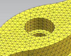
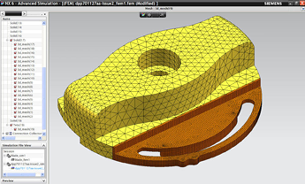
The new meshing tools within NX 6 allow you to mix and match mesh types. Here, a standard mesh is used for the central component of the button, but the portion of the design which undergoes non-linear behaviour (through deformation) is meshed to allow it to be simulated correctly.
This is really the crux of ST within NX. The system has never been as reliant on History-based modelling processes as other systems, so the development team has been able to integrate this new feature-based but History-less way of modelling into the very core of the system. Essentially, you can work with geometry to create the forms your need in terms of parts and assemblies, then start to add the dimensions, constraints and other relationships to the geometry to bring higher levels of intelligence. In the NX environment, this intelligence is built into your product models using DesignLogic and Expressions tools. These are a step beyond simple geometry parameters and add real design intent and knowledge to your model.
Starting with a basic form, then using the various tools (dimensioning and constraints) to tidy it up, it creates a finalised model that conforms exactly to your requirements, but with the ability to make edits just as you would earlier.
User interaction
The last few releases have seen the NX UI advance at a phenomenal rate in terms of usability. While that’s a general term, what I mean in this instance is two things. Firstly, the underlying architecture of commands and operations were completely rewritten in the last release, so many working methods and practices are now common and shared between commands. As a result learning times are cut (as knowledge of one command gives you an immediate head start with ones with which you are less familiar). Taking this further, the presentation of commands was reworked to provide you with a very clean interface.
The majority of commands are driven from the same rail-based dialog, which only shows itself when needed. This in itself is a high productivity booster, but when combined with work done to make the modelling process much more engaging and based on the 3D model rather than the dialog, this means that working with the system is much more intuitive.
This release extends the use of ‘on model’ working further in several areas. Firstly, the radial toolbars have been extended greatly. Menus can be accessed in full (using the ALT key), multiple layers of context sensitive commands are available at the cursor and, when combined with the new ways of working introduced with Sync Tech, then you have an extremely intuitive system.
There have also been a couple of updates that I think most users are going to love. Firstly, you can now switch into Full Screen mode, which, with the rail-based toolbars and new at-cursor menus, gives you a huge working area. Alongside this the new TrueShade mode displays your geometry with realistic materials, shadows, a range of preset lighting conditions and reflective floors, all without the need for high-end graphics.
Simulation
Alongside the UI updates and the introduction of Sync Tech, perhaps the biggest area of concentration most likely to excite existing users is simulation. For those unaware, NX has evolved from the amalgamation of the Unigraphics and I-deas products sets, alongside Siemens’ release of NX Nastran. The combination of the three means that Siemens’ development has had access to some of the world’s leading simulation technology and this has been integrated into NX pretty consistently over the last few years.
One of the core underlying updates to simulation is the way that the various components have been restructured for reuse. When conducting simulation tasks you now create three files that are linked back to the originating data. The SIM file represents the loading and boundary conditions, the FEM file contains all of the work you do to clean up the model such as abstraction, where features are removed or suppressed for simulation purposes, while the POST file is where you store everything in terms of result extraction and visualisation. This means that sections of the process are much more reusable. In addition, the new Glue Contact operation allows you to mix and match different mesh types for different sections of a single part, so that parts perform as they would, using intelligent choices.
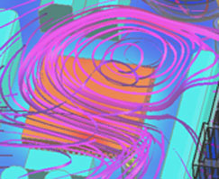
The new NX Electronic Systems Cooling package can now simulate condensation and dust/particle impact as well as the couple flow/thermal characteristics of an enclosed electronics system.
The example shown in Figure 2 is a toggle switch which uses deformation to lock the switch into certain positions. Now, while some portions of the component undergo large-scale deformations, the majority do not, so why run the whole thing as a non-linear (and inherently more complex) simulation. These new tools allow you to set-up the component (with materials and loading conditions), but sub-divide the component into those that undergo linear and non-linear deformation. The job runs as a whole and with ease, but you’re conducting what would traditionally be a very complex multi-physics simulation.
The simulation of sheet metal parts is something that many users are probably interested in, considering its increase in popularity these days, but as with many such things the actual process of simulating thin wall thickness parts isn’t quite as easy as it could be. This area has some attention for this release with the introduction of mid-plane modelling tools to assist in making it easier. Mid-plane modelling is a commonly used method of constructing thin walled FEA models. Instead of defining the complex geometry, a thickness value is assigned to the elements when meshing. Problems arise with complex geometry where the mid-plane is not readily apparent and gaps occur.
NX 6 introduces tools that allows the user to re-stitch, match and merge edges, creating a cohesive form that can be meshed. Some of the tools aren’t associative but the tools get you most of the way there, assuming massive topology changes aren’t made, only a swift clean up.
Click here to see an exclusive Develop3D NX 6 Workflow
Product Template Studio
There have been two areas of work that allow for design to be formalised and enables more re-use in a controlled manner. The Product Template Studio allows for the publication of a part’s parameters that drive its design, typically authored with Knowledge Fusion, in a very usable format using standard templates. Taking the parameters, geometry and expressions that control part of the selected part, you can then add an interface for those reusing that data. This can contain links to CAD entities (so highlights are shown on the model) and all manner of supplementary information. This can then be stored within the part file, so it is available in the assembly modelling mode and you can start to build intelligent template driven-assemblies that combine all knowledge of how that product is built up.
Closing thoughts
To be honest, we’ve barely scratched the surface of NX 6. What we’ve done is look at the updates which resonated most. What should be clear is that NX is continuing on a very aggressive development schedule that has continued over the last couple of years. The NX 5 release saw building blocks introduced (in terms of Direct Editing) which now make so much more sense in the context of the Synchronous Technology release. What we have now is a system that is very interesting in terms of modelling approaches.
For me, the introduction of Synchronous Technology within NX is much more exciting than Solid Edge. The reason for that is that NX has always allowed you to work with a much wider selection of modelling methods and has always supported the ability to intelligently link your part geometry to your design intent at a very granular level. This release sees this heightened.
Everything seems to be working in a much more connected manner. From the outset of the design process, the updates with Geolus technology mean that you can reduce your design overheads by making it easy to find components that can be reused as is, or adapted to a new purpose. The new Sync Tech based modelling tools then give the ability to model in a much more flexible and free manner, alongside the traditional parametric tools, as well as the surface-based modelling tools that have been a mainstay of NX for years. Then there’s also Simulation, which is really impressive.
With the NX Nastran solver as the foundation technology, Siemens is doing a great job of allowing you to take advantage of some pretty advanced simulation tools right at the design stage of the process and doing so in a manner that most users can take advantage of.
Next up there’s production and manufacturing. NX has always had a rock solid reputation in machining and mould design circles, purely because it’s one of the rare systems that has combined advanced CAM functionality with supremely capable modelling tools adapted for mould and die design.
NX doesn’t seem to get much in the way of coverage these days, but when you sit down, take it all in and look at what’s been accomplished over the last few years, it’s clear that if you’re looking to adopt a product development and manufacturing system that really can cover everything from conceptualisation, right through to production and beyond, then NX is a serious contender. The introduction of Synchronous Technology means that the pain associated with learning a new design system is eased somewhat and that should certainly drive new adoption. Those evaluating 3D tools are often scared off NX because of its sheer size. However, when stripped back to its ability to intelligently create a 3D model of a product in development and capture everything that relates to that process, then it’s amongst the best systems currently available. When you realise that you have the ability to work in a single environment to take a product to market, then it becomes even more compelling.
| Product | NX6 |
|---|---|
| Company name | Siemens PLM software |
| Price | On application |


