Delcam is a name that many are familiar with, but it’s still best known for its high-end, mould and die focussed CAM offering, PowerMill.
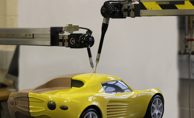
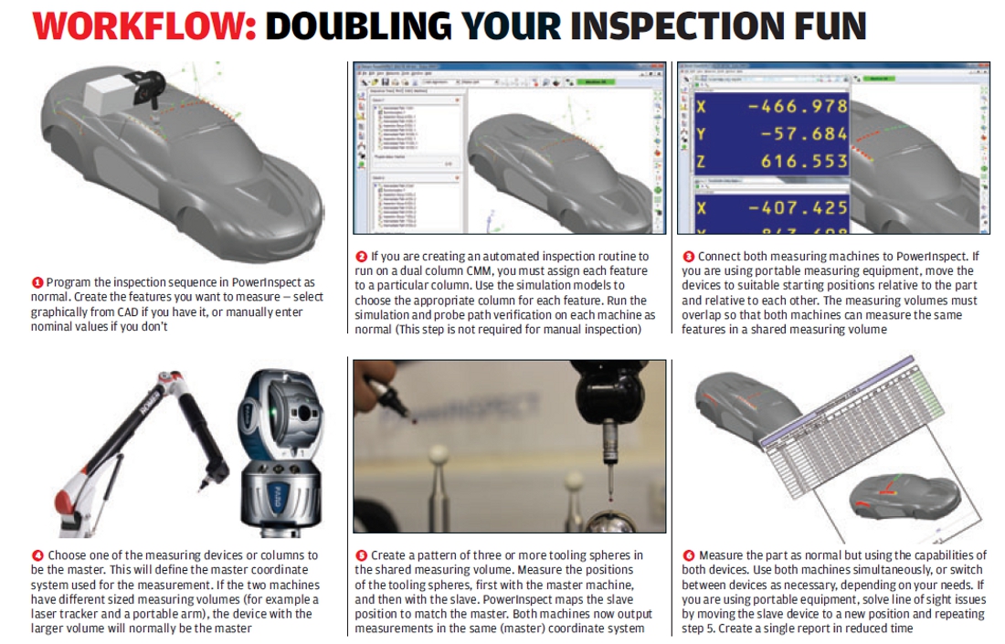
Fig 1. PowerInspect 2013 will allow the use of multiple devices in the same metrology process
While this still remains a core focus for the company, it has always had a much wider set of products that are worth exploring.
From PowerShape for design and shape definition, through a range of specialist applications (who else has footwear design specific systems), a range of CAM systems (such as PartMaker, FeatureCAM) and other systems that support the part production process.
One of the systems in the latter category is PowerInspect. Since its first release, one of PowerInspect’s strengths has always been its ability to support the rapidly growing world of metrology devices available.
While the coordinate measurement machine (CMM) has been the industry gold standard for many years, we’re now seeing a growth of all manner of devices used to inspect a product’s manufactured form compared to the CAD-based nominal.
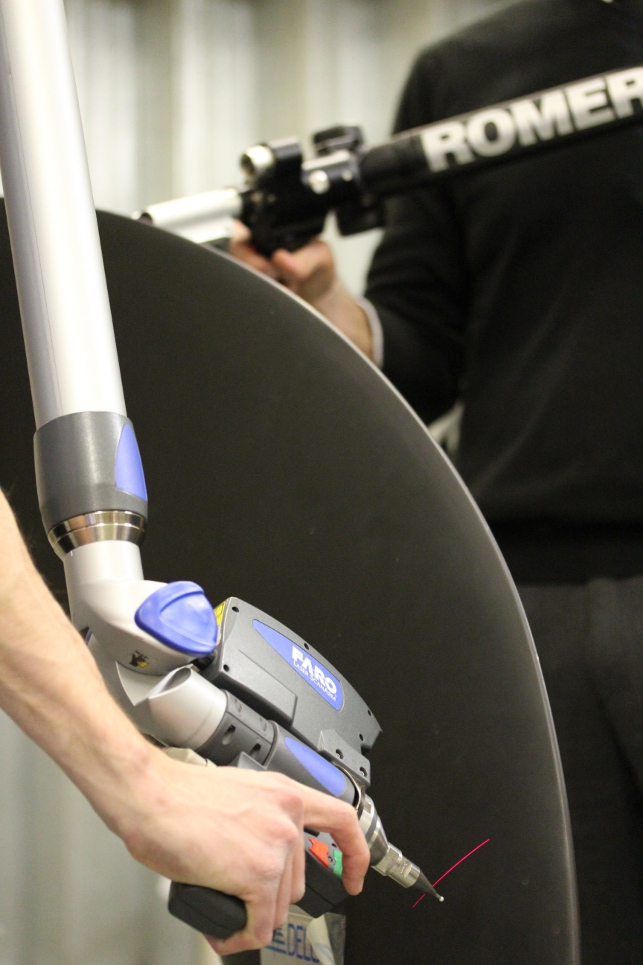
Whether it’s arm-based hard probes, laser scanners, camera trackers — the world of metrology is opening up as companies realise the benefits of these more portable methods and accept their accuracy as sufficient for the inspection process.
What’s also changing is how these devices are being used. As we’ll discover, many organisations are looking at these costly devices and seeking new and inventive ways to supplement and enhance a much wider range of tasks and workflows.
But to begin, let’s look at one of the major foundational updates to this release — the ability to work with more than one inspection device at a time.
Multiple device inspection
It may seem a little odd to want to have two inspection devices running in parallel when you first consider it. But after a little consideration, the need, and the reasons why some companies are requesting it, becomes clear.
If you step away from the idea of using a CMM device and into the realm of on-site inspection of large objects, then it becomes obvious. Today, it’s possible to combine longer range devices such as laser trackers, capable of inspecting very large objects, with smaller devices for localised measurement.
A perfect application for this is when you’re using an optical inspection method (either a camera tracking system or a laser tracker) where ‘line of sight’ is required for the measurement.
You can perform overall measurements with the laser tracker, but use a portable arm with hard probe to reach enclosed areas — such as under the bonnet, or inside the wheel arches — that would otherwise be difficult or impossible to measure.
Another example is the inspection of a train carriage. The coach work might not have such tight tolerances, but if you’re looking at the rolling stock, then you’re going to need something that gives the accuracy you need.
Someone could be doing the gross inspection with one device, while someone else does the detailed work with a more accurate machine. Other examples could be in the marine industry or aerospace — pretty much anything big! Again, you can supplement one device with another, without having to move, set-up and measure the first device.
The set-up process is pretty simple. It works on a Master/Slave basis. The first device is set-up as normal in PowerInspect, then the secondary device is registered to it so that both are aware of their position.
This can be done in a couple of ways, but using metrology spheres at a known position is typical — it really depends on what tools you have at hand and the job you’re trying to do.
Once done, you go at it. Other systems may support the use of multiple devices, but PowerInspect is the first system I’ve come across that allows you to work with both at once, rather than having to switch between the two. And it’s device independent as well, so you can mix and match different types of equipment from different manufacturers.
Single bed, multiple columns
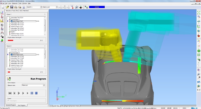
Another application that Delcam showed in its rather impressive inspection lab (if you’re ever in the Small Heath area, it’s worth a look) is having two CMM columns and probes installed on the same CMM table — one either side (see figure 1 for an idea of how this looks). This is used for automated inspection of larger components that are broadly symmetrical.
Now, the idea of a numerically controlled inspection routine is nothing particularly new — many vendors have been doing it for years and it’s established practice for many.
PowerInspect has supported it for a good long while — reusing a lot of the knowledge Delcam has from all things CNC, of course. What’s different with this is that with two probes, working simultaneously on the same part, you have a much greater potential for error.
Firstly, the issue of driving an expensive probe into a metal part is to be avoided at all costs (although sometimes the part is more easily damaged and expensive to repair than the probe!) Now with an extra probe ‘on the go’ you need to ensure that the probes don’t collide with each other — not just the work piece.
And this can’t be achieved on a pure simulation basis — the machines may run at different speeds either deliberately or as the result of part variation. So the system needs to be able to look ahead and see the effect of each moving part’s motion. Figure 2 shows the collision avoidance zone for each head as a rendered volume.
Sychronisation points can also be added, so that one probe can wait for another to finish its task at hand (perhaps to solve a clash issue) before they both continue.
Applications can vary but Delcam has developed this for the automotive industry (remember, inspection specialists, Renishaw has a 20% stake in Delcam too) and the vision is that this is used to speed the time required to carry out inspection of automotive body panels in a production environment or aerospace components.
It might sound like a complex solution, but having two probes working concurrently, with efficient routines, could strip hours out of year’s worth of inspection tasks that are repeated.
Automotive styling
Now that we’ve learnt how PowerInspect is used with two devices, perhaps it’s time to explore some of the more industry niche uses of this type of technology.
One area in which Delcam has seen particular activity in is the reuse of CMMs in non-traditional ways at automotive OEMs, specifically, in their styling studios.
Delcam has put together a set of new tools under the name PowerInspect Design. As most readers will be aware, while the rise of the digital mock up and high quality visualisation tools has continued, most automotive companies still swear by their clay models.
It’s in this, seemingly archane, and highly specialised, world that CMMs are stepping out of their norm and supporting a couple of very specialist workflows.
The first is when it comes to capturing points and curves from a complete model to assist with build A class surfaces. You might think that in this world of laser scanners that can capture millions of points in minutes, the creation of surfaces from a physical model is a done deal. You’d be wrong.
Most car stylists are looking to capture input from the clay model in a very spare manner — and PowerInspect is evolving to support it. Without getting too bogged down in the details, it works like this.
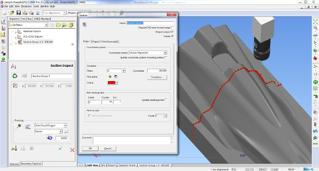
Once the clay is in a fit state for reverse engineering, the CMM is used to extract a sparse set of points across a predefi ned set of sections. The CMM’s work axis is locked and the points captured.
What Delcam has done is allow the user to define specific points that are being captured. For example, auto-designers want to know where a surface breaks (perhaps for glass house) or where there’s a sharp change in tangency.
PowerInspect allows you to flag these up as you work across (or up and down the model). The end result is a network of curves, driven by a sparse set of points, which are then used to build those stunning, high quality surfaces.
The second workflow is, on the face of it, even more peculiar. We’re all used to the concept of using a CMM to measure material that has already been cut – typically by CNC machine. But the automotive styling crowd have found a way to flip this on its head.
It follows on from the idea that you can use a CMM to capture design points for surface development. But what about in reverse?
Imagine you have your rough clay model, but want to place precise reference points into that clay so you know the limitations when you are creating, smoothing and refining that clay surface.
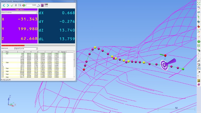
What these new tools allow is to drive the CMM to put marks into the clay, with a knife attachment, to the required depth (known as marking out). It gives precise control, exactly where the stylists want it, so they can then work their magic.
If a particular region has been finalised and the CAD model exists, you can attach a milling head and machine the component directly, driving the machine exactly as if it was a router. It simply allows you to create the component in the easiest and most efficient way- again maximising the effectiveness of the equipment that you have available.
OMV & other updates
We’ve just about got enough room to rip through some of the other updates to this PowerInspect release before we finish.
This release sees the work on reporting tools continue. This is never more important when you consider how many companies are looking to automation in their inspection processes.
The updates to reporting this time around centre on making dimensions and presentation more clear. PowerInspect has always done a pretty good job of this, but a few tweaks (such as showing angular dimension in the traditional manner) make them easier to read for the non-technical.
Another area is On Machine Verification (OMV), which describes the act of combining machining processes with inspection for a couple of purposes.
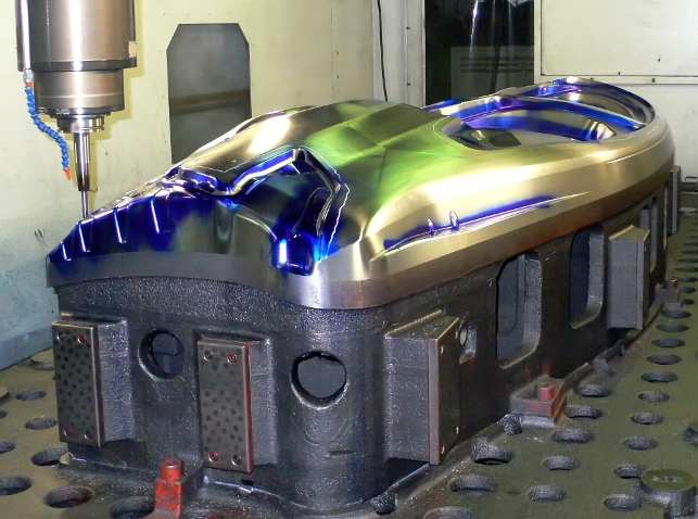
The first is to allow mid-manufacture inspection. When you’re working on larger projects (think stamping die perhaps), then the use of an OMV set-up will allow you to check against the CAD to see how things are progressing. Obviously catching any areas for concern or error earlier on in the process.
The other application is to assist with part setting and location. Using OMV techniques, it’s possible to adapt the NC toolpaths to the position of the part, rather than the other way around.
While we don’t have time to get into the specifics of this, it’s a growing trend in both automotive and aerospace.
PowerInspect now supports not only probe heads attached to the CNC machine itself, but also the use of portable measuring equipment as well.
Conclusion
PowerInspect 2013 is a pretty impressive release for a couple of reasons. The first is that it brings on-line some techniques that truly do show how organisations take a technology stack (multiple measurement devices) and run with it.
The seemingly simple act of adding dual device support brings a whole load of downstream benefits that are widely applicable in some cases and highly specialist in others.
But what it also shows is that there’s a will amongst the metrology community to make more use of these devices once they’re invested in, find new ways to work, new workflows and new processes. And Delcam is providing that community with a tool that allows them to do it, without restriction to which particular hardware they’ve invested.
On Machine Verification: Cutting manufacturing time in half
The introduction of Delcam’s PowerINSPECT On-Machine Verification system has allowed Taiwan’s leading press tool manufacturer, COC Tooling & Stamping, to halve the time needed to manufacture its tools.
Established in 1990, COC now employs around 450 people on its 50,000m2 site in Taoyuan County, Taiwan, where it specialises in tooling for large automotive body panels. These tools are supplied to major manufacturers, including Ford, Nissan, Toyota, GM and Mitsubishi.
Company President, Mr. Y.K. Tseng, explained that the introduction of PowerINSPECT OMV had produced enormous increases in productivity.
“With On-Machine Verification, we can measure the press tools on the machine and find out immediately if there are any problems,” he claimed. “We can obtain a direct comparison with the CAD model, which is much more reliable than using inspection methods based on drawings.”
Most of the machine tools at COC are between four and five metres in length, and many of the press tools being manufactured are of a similar size.
“Moving parts of that weight and size to the CMM for inspection used to be extremely difficult and slowed down the whole production process,” said Mr. Tseng.
The main problem with these large tools is that the longer cutters needed to machine to their full depth can be pushed out of alignment, especially near the bottom of the part. This gives an oversize surface on the punch, while the cavity will be undersize.
“Previously, because of the problems in setting up the tool back on the machine, we would use hand finishing to correct any errors,” remembered Mr. Tseng. “This wasn’t very accurate and was also very time-consuming. Now, we can re-machine the surface on the machine tool, which is both faster and more reliable.”
This higher quality can be seen in the much reduced try-out times needed for new tools. “We can now be confident that the tool will work as soon as it comes off the machine,” claimed Mr. Tseng.
| Product | PowerInspect 2013 |
|---|---|
| Company name | Delcam |
| Price | on application |