modeFrontier 2014 – Simulation is one that’s split into multiple different solvers, each with their own area of specialism. Al Dean looks at a system that allows you to bring these different solvers together to perform a much more holistic optimisation
It’s a curious fact that the products we design, engineer and produce often have a varying number of operating parameters.
Whether it’s structural and mechanically, thermal or aerodynamically led — or most often, a mix of two or more — are what defines whether that product is successful in providing the required operation conditions.

Fig 1. modeFrontier gives you a schematically led environment to build optimisation routines that link into CAD and a wide variety of simulation solvers
The curiousity lies in the fact that the tools we most commonly use do not reflect this mix. Solvers are specialised beasts, looking to bring clarity to a specific segment of those operating conditions and performance criteria.
This is why we have separate fields for Computational Fluid Dynamics (CFD), Finite Element Analysis (FEA), Noise and Vibration Harshness (NVH) et al.
The issue is that these neatly compartmentalised solutions don’t really fit with the products we’re looking to simulate.
While its entirely possible to conduct individual analyses using each set of tools, when you’re looking at optimisation, you need to be able to have the results from each discipline feed into each other — otherwise you’re looking at a very cumbersome and time consuming process.
Yes, multiphysics is something that more and more organisations are looking at, but again, the process is complex and time consuming, made infi nitely more complex when you consider that most simulation tools are not exactly open to working with systems from outside their own stable.
It’s into this environment that Italian outfit, Esteco, introduced it’s modeFrontier optimisation system. The goal is that modeFrontier provides an environment in which an organisation can pull together the discrete simulation tools it has available, along with 3D modelling systems, and allow you to set-up optimisation studies that take inputs and outputs from each to achieve the optimal result.
We’ll get onto the methods it uses to derive that result in a little while, but first, let’s look at the set-up process.
modeFrontier – schematic set-up
modeFrontier, during the study set-up process, uses a schematically led user interface (UI). You’ll find the usual array of panels around the central scheme.
These give you access to all of the various different nodes that can be used to make up your study. The high level idea is that you drag and drop the components you need, connect them up and the system works its magic.
Fig 2. modeFrontier uses a Pareto Front approach to give a range of solutions that solve your design and engineering goals
In terms of workflow, let’s look at it from the basics. A good starting point is to define the inputs, output and goals that are driving your optimisation study. Because modeFrontier works independently from the solves, it’s key that things are defined here, then connected to the engines that drive or use them.
A good example of this is the core geometry model that you’re going to use. As we’re all familiar, CAD systems are typically parametrically driven and those parameters are available to be driven from external systems. In modeFrontier, you begin by defining the inputs that are used to vary the geometry and subsequent simulation studies.
Each is defined in the UI separately with the bounds/limits as well as any discrete values that are available for the optimisation iterations.
You then use the built in connectors to build the links between those modeFrontier inputs and the parameters in the CAD system. This is done using a pretty simple dialog to map between the two — using similar naming conventions will help massively.
You can see from Figure 1, that the Catia node connects directly to the modeFrontier inputs. A similar process is used to define other inputs and outputs. Again, in figure 1, you can see the outputs defined as constant stress and mass (this is a lightweighting exercise). It’s also used to define transport mechanisms — in this instance, between Catia and Abaqus, but this could be from SolidWorks to Ansys, to a CFD code, whatever you need.
Once you have the mechanism in place to pass data between the various systems, you also need to address how the optimisation is conducted. Again, modeFrontier lets you drag and drop the nodes you need. This might, for example, be a Design of Experiments node. You also need to set-up the optimisation strategy — of which there are many.
The system will give you the best option based on your study, but these, of course, can be adapted to your requirements when needed.
One of the problematic areas of this type of work is ensuring, as best you can, that the complex schematic and workflow you’ve created actually works. At all time, modeFrontier monitors the logic and gives you feedback, showing where issues might be found.
Once things are ready, the system can then be run. modeFrontier will then work through each possible iteration, streaming the results to the interface. As shown in Figure 3, you can see each iteration as it completes, see where it lies on the Pareto Front (more on that in the next section), see where things have passed or failed and generally keep an eye on proceedings.
As you’d imagine, this type of work is computationally expensive, but the system has the ability to not only load share in ad hoc manner, but also take advantage of separate computational facilities you have — so the software used doesn’t need to be loaded on a single machine.
modeFrontier – post processing
modeFrontier is based on a Pareto front approach.
Fig 3. modeFrontier can automate many of the processes that are needed, from documentation assets (images and video etc.) to full CAD models, in native or exported formats
The gist is that instead of giving you a single or limited number of iterations or variants that solve your design goals, it accounts for the fact that decisions based on multiple inputs and goals are complex and gives you access to a spread of solutions that will give the desired performance characteristics.
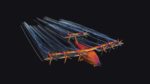
This Pareto Front is relatively easily visualised. Figure 2 shows a typical result where strength is plotted against weight and the most optimal solutions are show in red on the chart).
While I don’t want to get into the specifics, the system is focussed on the concept that you eliminate the solutions that don’t match your criteria, then use a set of tools to filter, narrow and refine the acceptable results. You then use that smaller number of variants to make your final decision.
modeFrontier’s post processing tools are first class and with a little set-up work, you can automate much of their creation.
Charts and plots are available and have built in filtering tools to narrow down to the final shortlist of candidates (Figure 4 shows how each input influences the results and how variants can be filtered out from the results).
Using the same tools, you can also have the system create assets for documentation of your work, as well as to retain CAD models built during the process, to remove unnecessary remodelling work to progress designs further.
In conclusion
modeFrontier is a marvellous system that gives engineers the ability to connect up the disparate technologies that they typically have in-house and conduct optimisation studies that take into account much more than would be possible using discrete systems alone.
Fig 4. modeFrontier includes a wide range of plotting tools with live filtering to narrow your solutions down
While it’s possible to do this kind of work if you have all of your solver technologies from a single supplier, we know that many engineering led organisations don’t have a single supplier and run with the best tool for the job.
What modeFrontier does is allow you to achieve that level of integration, but without having to change the systems you use.
To gain a deeper, richer understanding of how the various inputs into a products’ performance influence its behaviour and performance, we’re going to need a new set of tools that enable it. modeFrontier is one such tool and it represents a way to get the best of both single solvers and working with all those at your disposal to get the optimal product.
| Product | modeFrontier 2014 |
|---|---|
| Company name | Esteco group |
| Price | on application |