If you were to believe the hype, the act of 3D printing a component or set of components is as simple as loading the data file, switching on your machine and away you go.
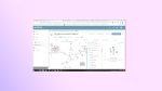
Fig 1. Magics’ 3D nesting application can optimise stackable build chamber layouts
The fact is, as anyone who’s done this first hand knows, this is complete and utter nonsense. For those that have been actively building their own parts using the diverse range of technologies available, you’ll be aware that each machine and process type has its own requirements, limitations, tweaks and best practice.
There are also a number of common place tasks that aren’t immediately obvious, whether it’s the need to split larger parts into chunks that fit into your machine, the need to compensate for z level contraction of parts after building or just fixing bad STL data.
While many of these quickly become apparent when you dive into 3D printing for the first time, many will emerge with time. And not everything can be solved with the included software or the CAD tools we use to initially create the 3D geometry in the first place.
This is where Magics steps into the fray. Developed over the last 17 releases by Belgian wizards of all things 3D printing, Materialise, it’s become the de facto standard for those at the business end of 3D printing.
Not only does it include a huge range of data fixing and manipulation tools to ensure you get the best part geometry, but increasingly supports the build process for those with industrial level requirements in terms of multiple machines, multiple materials and a heavy throughput.
Getting the basics right
The STL file format is the lingua franca of 3D printing — it’s not ideal, it’s a tricky little bugger at times, but it works.
The problems often pertain to how they’re generated, rather than the formats themselves. With any tessellated format and particularly with complex, organic shapes, triangles can be flipped, can intersect or just be plain missing. Any of these can play havoc with your 3D print process.
Magics includes tools that allow you to take in STL data and fix it. No matter the problem, no matter how bad it is, the chances are that Magics will fix it — either with automated tools or allowing you to dive in and do it manually.
If you’re bulk loading data, it’ll allow you to work through each component at a time. It’ll allow you to split up those STLs that are output in a single lump.
For those that are building scale models, particularly those in perhaps the oil and gas industry or the architectural design world, there’s also a set of tools to assist with the effect of scaling large models.
This centres on the fact that if you scale down a model of a housing complex, for example, that action also scales down wall thicknesses to such a degree that would be typically unprintable.
The tools allow you to add thickness as well as to bring together the whole model into a single entity (rather than separate geometry sets for walls, doors, roofs etc).
Working with large parts
Another key issue that Magics provides tools to overcome is working with parts that exceed your build volume.
While machines are getting bigger in their capacity, it’s often the case that you’ll have a couple of components that simply don’t fit. Of course, one option is to dive into your CAD system, split them and add in fixtures (think: dowels and such), but Magics does the job more efficiently.
Fig. 2. Magics includes all manner of tools to assist with cutting, splitting and adapting large components to fit within a specific build envelope
Figure 2 shows an instrument panel that needs to be split into three components to get it into a single build. Magics allows you to simply sketch in a polyline which is then used as the basis for the split process.
An offset can be added into account for adhesive and the ends capped off. Then it’s a simple case of joining them once they’re out of the machine.
Optimising the builds
Once your data is ready, it’s time to explore the master of Magics when it comes to making the most effective use of your 3D printing hardware.
Most systems are supplied with a suite of set-up and preprocessing tools. The problem arises in that, particularly at the lower end of the spectrum, these aren’t too intelligent.
Most users would want to be able to build multiple parts in one go and ensure that the parts are not only built correctly (in terms of aligned to build layers) but that materials used and time to finish the build is as optimal as possible.
Obviously this is massively dependent on your hardware, so let’s break it down into two different camps. The machines that allow you to stack a build chamber and those that don’t.
Non-stackable machines
Most 3D printing systems work on the basis of arranging your parts on a platform in just two dimensions — parts can’t be stacked vertically.
Reasons are that these types of machines (from SLA to Objet to MakerBot) all require support structures of some kind.
Magics includes a number of tools to help optimise a two dimensional build platform and it works as follows. Load in all of the parts needed to build, orient them as you or its purpose needs, then use the ‘automatic placement’ option to optimise the build platform based on a machine’s capability.
What’s interesting is that, if you have multiple machines, it’s a snap to change the machine in use and relay out the parts. To do this, you begin with a model view with all of your parts and then work through the fixing and repair process.
These are then loaded into a ‘scene’. This scene takes machine parameters from a built-in library, which contains information on build platform, z-compensation and many other things, and uses this to build a ‘virtual’ build chamber.
A number of tools can then be used to have the system automatically arrange the parts on the platform to get the most out of your build. We used the example of a bicycle pedal on a MakerBot in our workflow on the right.
The automated nesting tools work in one of two ways — using a boundary box or the more compute heavy geometry to calculate the best positioning. Each machine will have different requirements in terms of gaps between each part and the machine library contains all of this information, but it can be fine tuned to your needs.
Once it’s done, you can then export an STL of the whole thing (if you need to run it through a machine’s software) or use Magics to actually control the machines themselves.
It’s this latter process that is partly the reason that those at the very bleeding edge of 3D printing have long been using the software.
Stackable build chambers
Now, if you’re using a powder-based system such as sintering machine or a Z corp etc., these typically allow you to stack out a build chamber in three dimensions, rather than just two.
However, this presents quite an interesting challenge when you’re looking to optimise a build. Handily, Magics also includes a set of tools to help with this too — and they spread across a number of different tools.
Magics also has a growing set of tools to assist with working with metal 3D printing processes
The first relates to the nesting of parts in three dimensions. Again, Magics has a number of tools, led either by a bounding box around each part or using specific geometry. It has controls over how the system can translate or rotate each part (again, helpful for maintaining an orientation). It also includes tools for handling small and large parts in the same build.
Larger or more dense parts tend to retain heat more than smaller parts, so you typically need to have more distance around these components to avoid warping and deformation.
One aspect that’s also worth covering is that of a Sinterbox. This relates to when you have a set of parts in a large build chamber that you want to retain together in a group.
While Magics enables you to group parts, when you’re breaking 300 parts out of a cake of powder, it’s difficult to track which parts are where. Sinterboxes get around this by giving you tools to create a mesh-like box that surrounds those parts that need to be kept together.
The workflow below shows this in action. Magics enables you to nest a specific set of components, build a meshlike box that surround those parts, so they’re kept together when you break out the parts and post process them.
Metal components
It’s worth mentioning the tools available for working with metal components. This has been around for a while, but will become more key for many as more machines become available.
Metals have very different requirements in terms of pre-processing and Magics supports them. Much of this relates to controlling where and how support structures work — to work around some of the thermal issues involved that simply don’t exist when working with plastic materials.
In conclusion
Magics is targeted at the professional 3D printing user and rightly so. If you’re running a machine that cost a couple of grand, it would be hard to justify more than that on the software alone.
But if you’re pushing the boundaries of what can be achieved with a variety of 3D printing devices and materials, it’s worth knowing that it exists and has tools to help when the time comes.
While there are other systems out there that might cover specific portions of what Magics does, there’s nothing else on the market that has such a complete mastery of the whole process.
It runs from STL fixing, editing and adaptation, through build preparation and into complete control of the process, with a set of tools that can only come from the company’s experience in all facets of the process.
| Product | Magics 16 |
|---|---|
| Company name | Materialise |
| Price | on application |