Siemens PLM software has been through something of a renaissance over the last few years.

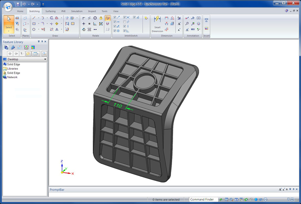
A new 3D model relationship in Solid Edge ST4 lets users apply horizontal or vertical relationships to faces of completed native or imported parts
The introduction of Synchronous Technology across its 3D modelling portfolio has perhaps benefited the profile of Solid Edge most.
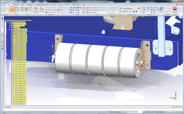
Combining the traditional history-based modelling technologies with direct modelling techniques that remove the reliance on order design process, Sync Tech was, and still is, big news. However, Solid Edge has also been growing in other areas and alongside its mastery of sheet metal design, the system has been garnering new tools to help with complex and very large assembly design. Additionally, the Velocity Series is seeing Solid Edge bundled together with Teamcenter Express, Femap and NX CAM.
The latest release – Solid Edge ST4 – has been through some serious rework in terms of user experience. Sync Tech has brought with it a new, more dynamic interaction tool, a new ribbon-based UI and many more goodies. The release also sees the visualisation tools get an upgrade to all the current standards, reflections, mirror-like ground planes, shadows and such.
It’s clear that the technology is evolving with each release. The last three have seen pretty dramatic updates and reworks of the technology that have enabled the user to mix both history and non-history based modelling tools. But for ST4, the development is much more incremental, a good indicator that the technology is reaching a level of maturity.
For example, the definition of revolved features now uses the steering wheel widget, a core part of the Sync Tech interaction. There’s a new tool to create holes or shafts (using a tangent plane and point). On the subject of the shaft design, the dimensions used to define the revolve in sketch form are now automatically transferred to the 3D model, enabling direct edits where needed. Elsewhere, the definition of web and ribs has also been reworked. The system requires a 2D sketch, but from them on the thickness, depth, draft angle are all defined using the dynamic tools.
The new 3D offset relationship is super handy for creating and maintaining assembly features accurately, such as slots and other guides. It can also be used to maintain the mid-way relationship between two existing features. It’s this type of thing that makes Sync Tech sing. They can either be defined in a 2D sketch and transferred to the 3D model or defined and adapted whilst modelling.
Finally, on the steering wheel/Sync Tech front, the rather useful widget can be used to reposition and/or copy both parts and sub-assemblies dynamically, with new assembly relationships being created on the fly. This should make the positioning of multiple instances of a sub-system somewhat easier.
The last update we’re going to look at that’s applicable to all users is the addition of a new online parts catalogue. While every 3D design system worth its salt has a parts catalogue, many of these are offline, static affairs, only updated with each release, if at all.
By tapping into one of the leading web-based purveyors of standard and manufacturer specific parts (cadenas.co.uk), Siemens PLM Software is making the whole thing much more dynamic.
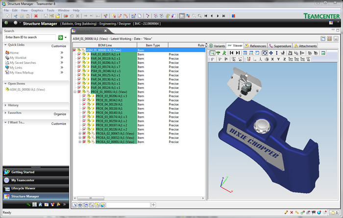
Teamcenter integration
Since the launch of Velocity Series, Siemens has seen a pretty strong adoption of Teamcenter in its user community. This is particularly driven by the Express version, which delivers out of the box, pre-configured workflows. ST4 brings greater integration between the design system and the PLM world on several levels.
The first is that there’s drag and drop links to Teamcenter. Open an assembly, drag it into Teamcenter and the parts, assemblies and associated data become managed data.
The second is that within a Teamcenter managed environment, Solid Edge can now take advantage of JT data, both with native data in the context of third party data from other systems. If you’re unfamiliar with the system, the JT format was developed by Siemens and is soon to be incorporated as part of an industry wide standard led by the ISO organisation.
To explain further, it’s now possible to have Teamcenter automatically convert imported data from other systems into the lightweight JT format. This can then be used, referenced and linked back to the originating data, within Solid Edge. Of course, it may be the case that some form of redesign work takes place based on that data. In this instance, the data can be saved as a new version, but the link will be broken. Re-establishing that link (to maintain traceability) can be done manually at the source.
A final few things on the Solid Edge/Teamcenter integration are that, firstly, frame/pipe lengths are now reported based on cut length. This allows stack and procurement to be gauged much more accurately. Secondly, the Teamcenter search tools in Solid Edge have greater automatic filters, such as showing the first 30 items. This enables the user to get to the data needed without having to filter through all the search results.
Alongside the third party data tools described in the context of Teamcenter, this release also brings new import tools for vanilla Solid Edge. It can now directly read SolidWorks and Inventor data (both parts and assemblies) and there are a couple of updates if working with AutoCAD data. The new version also retains multi-line text and has improved geometry and block origins are matching.
Drafting
Solid Edge already has a pretty complete set of drafting and annotation tools – as to be expected from any system that’s been on the market for over 15 years. As with many such systems, Solid Edge has reached a level of maturity so updates tend towards giving the user full control over annotation style and formatting – no bad thing in my opinion.
This release sees new options for control over formatting of tables, to skip hatching when passing sections through rib and web features and there’s new control over how balloons stack when adding part numbers to fastener stacks.
Conclusion
As we’ve discussed, Solid Edge is going through something of a renaissance. While early on in the mid-range 3D design tool battles, the system seemed to quickly lose ground to SolidWorks and then Inventor. These days it seems to be holding its own. No, it doesn’t have the huge user bases of either of those competitive systems, but it’s now showing up on more people’s radars than previously. Solid Edge has always been a technically very proficient system and the last four years have seen this continue, expand and move into new areas.
Synch Tech in the context of Solid Edge is maturing nicely and we’re seeing the lines between the ‘Ordered’ and ‘Synchronous’ commands start to blur. A good example is the updates made in this release. These see the benefits of a traditional approach (using sketches), combined with both direct-style editing, but backed up with intelligence retention that allows both fluid creation and more efficient editing when required.
The simulation updates are being driven by advances in the Femap product and some rather handy tools are now being transferred across into the integrated environment of Solid Edge, rather than residing purely in a standalone system.
All in all, Solid Edge ST4 is another rock solid release and, for both existing customers and prospective users, perhaps looking at switching systems or adding to their toolbox, it’s worth serious investigation.
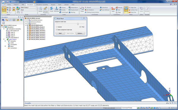
Simulation updates
The last Solid Edge release got a serious boost in terms of integrated simulation with the introduction of the Solid Edge Simulation module. This has been growing in terms of coverage since its release and now includes full part and assembly simulation). The ST4 release concentrates on the simulation of sheet metal components, often a tricky task.
The major feature that facilitates this is the introduction of mid-surface modelling techniques. This takes advantage of a method of reducing the complexity of a finite element mesh by using a single surface that represents the mid-point of the part in question, to which a thickness is then attached during analysis. This is further extended by the ability to bring together both mid-surface-based sheet geometry with more traditional solid meshes. The system will handle edge and face gluing so the most efficient method is used for the most appropriate geometry.
There’s also been work done on both beam elements, that again allow the definition of highly efficient models to be built that represent frame style parts and assemblies. The tools are built into the frame design environment and can be used to discover deflection and stress for parts such as I, T, C and box and C beams.
Other updates include greater control over meshing (with options for mapped meshing complex geometry in an orderly fashion) and refinement of the mesh in specific areas (such as the minimum number of elements on an edge or maximum on small faces). In terms of post processing updates, there are new options for the numerical formatting in of colour bars in contour plot legends and greater control over decimal place usage.
| Product | Solid Edge ST4 |
|---|---|
| Company name | Siemens PLM Software |
| Price | On application |