

With the release of Solid Edge and Synchronous Technology (ST) around this time last year, Siemens set in motion a chain of events that hasn’t been seen since the launch of parametric history-based modelling which was 20 years ago. We now have a situation where the dynamic editing of geometry, without having to worry about time-consuming history recalculation, is gaining ground in all areas of industry.
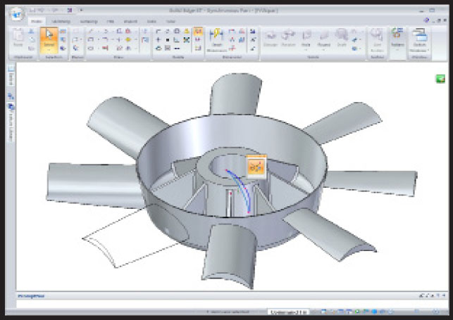
Siemens PLM has added Synchronous Technology to the helix, a complex geometric form that doesn’t lend itself well to direct manipulation. This image shows a helix shape for the blades as the first feature created with nearly instant changes
The introduction of ST by Siemens PLM brought a greater level of awareness to the market about the potential of such technology. While PTC already had CoCreate acquired, the original direct modelling application, and new kid on the block SpaceClaim had delivered its take on the technology, ST was certainly a catalyst for all that followed.
Dassault introduced dynamic editing with the launch of Catia V6, as did SolidWorks, although to a lesser extent with its 2009 release. PTC’s Pro/Engineer Wildfire 5.0 has learnt some direct modelling from CoCreate and Autodesk will shortly place Inventor Fusion on its Labs site for users to download. In short, it’s been quite a year.
We’re now about to see the launch of Solid Edge with Synchronous Technology 2.0 (ST 2) which is due to ship later this year (expected late summer).
Pushing Sync Tech further
Solid Edge with ST 2 sees the core principles established in the last release extended into new areas of the application. To recap, when stripped back, Synchronous Technology is about modelling geometry, often dynamically and often without features, but without the constraints associated with history.
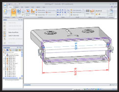
An example of Solid Edge’s Live Sections are 2D cross sections where 2D entities can be dragged or changed with dimensional control
Because there’s no history, calculation times are instant for most edits. The interesting thing is that it’s possible to still retain much of the power of parametric modelling, using specific dimensions and relationships to both add design intent and to drive design change (something which has been misinterpreted by many).
Look at the initial release, it’s pretty clear that it was just that – a formative release. The Sync Tech implementation was done with a basic set of commands and operations; those most suited to the technology (typically prismatic features – Extrude, Revolve, Hole, Round, Draft, Pattern and Thin Wall). Siemens couldn’t apply Sync Tech to everything that was in previous versions of Solid Edge, but that was never its intention. Instead version one was laying the foundations to offer a lot more power than the original short feature list might give away.
Despite the revolutionary nature of the new technology, users weren’t forced to use Sync Tech. They still had all of the power of the parametric, history-based modelling tools that had been in Solid Edge for over a decade. Sync Tech was never intended as a replacement or an end to traditional modelling techniques, but rather to create a fork in the road. The traditional tools would continue down one fork, while the Sync Tech-based tools forged a new path. What’s interesting is that now, with Version 2, there are links between these two paths emerging and it’s all becoming clear.
Modelling harmony
One of the key updates for this release has been the work done to change some of the fundamental problems that arise from direct editing. Feature-based modelling gives users the ability to store the explicit parameters, geometry and inputs to the creation of a specific feature. And while Solid Edge ST 1 had some basic features that were retained in the part file (such as holes and patterns), these were referred to as Procedural Features. These have been extended in this release to do one of two things: either to retain control over a geometry creation process or to allow it in the first place.
A good example of the former is how the system worked with draft. One of the big problems with any “direct modelling system” is that it is very easy to push and pull linear forms, with no draft. But when it comes to adding draft, particularly to complex geometry, then user could run into problems.
In Solid Edge ST 1, users could add draft with ease, but it was a one hit wonder and only worked with very basic geometry (the same is true of SpaceClaim by the way). As soon as the user rotates the faces to which the draft is applied, the ease of manipulation is lost. After all, if that process isn’t stored as a feature, it can’t be directly edited, and to reapply different draft would be rotating separate and individual faces. For draft operations in Solid Edge ST 2 the inputs and references are stored as a Procedural Feature and can be edited directly.
Another example of where traditional modelling techniques can influence geometry creation with Synchronous Technology is the ability to edit directly how fillets are formed at corners or intersections. You select the face, hit the button and you can switch between the two options – making life much easier, particularly if you, like me, always miss that one edge loop and have to go back selecting things again.
A perfect example of using features is found when looking at new ST-enabled capabilities. For this release in general terms, the addition of the helix is the big one. A helix is a complex geometric form and doesn’t lend itself well to direct manipulation. Solid Edge ST 2 stores the underlying sketches as part of a feature set, so you can edit them when you need to.
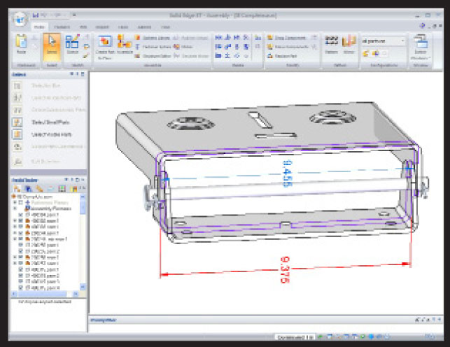
The new Live Section command allows the user to display a section through a part and then dive in to drag-and-drop the section geometry. The system instantly updates the 3D geometry that it is derived from. If Live Rules (on-the-fly constraints or relationship handling) or more formal constraints are set-up, the surrounding geometry will automatically update. If there’s a sticking point, it’s that it’s not possible to place a Live Section through a complete assembly, so working with multiple parts is a bit of a workaround – it’s possible to section one part and the rest of the geometry turns transparent.
Sheet metal goes ST
While the tools and updates I’ve already mentioned pertain to the core of Solid Edge’s toolset, this release also sees Synchronous Technology applied further and into the realms of task- or process-specific operations – namely, Sheet Metal design, which is perfectly suited to Sync Tech. Sheet metal forms are typically linear or planar in nature, and when the forms do get complex (typically at bends, folds and stamped features) intelligence can be used to handle K-factor and bend radii and geometry.
With the new release it’s possible to get working straight away, sketching out starting features, adding flanges, lips, cut outs and all that good stuff – directly and dynamically. This, as you would expect, is done using Live Rules and Live Section, and the implementation is excellent, particularly for a first bash.
The Live Rules and Live Section tools make it possible to work with geometry very intelligently, dynamically manipulating data into shape as required. There is a huge potential for editing imported sheet metal parts and the system will recognise the bends, folds and other features on the fly, allowing them to be edited. It also allows material to be switched. Solid Edge bases everything on the material properties being used in the model. An imported part designed in one material can have its material switched and the system will update the design, the bends and folds, and adapt to the characteristics of that material.
That’s hugely beneficial for those working in a subcontract environment. It might sound a small thing, but it could mean the difference between a part fitting or not.
Simulation
Alongside the updates made to Synchronous Technology, the good news is that Siemens has also been working on other tools, irrespective of which modelling methodology is used. This release sees the introduction of the Solid Edge Simulation. This is intended to bridge the gap between the Femap Express tool provided with the Velocity Series and the jewels in Siemens’ simulation crown, Femap (a pre/post processor) and NX Nastran (the industry standard solver code).
Solid Edge Simulation offers an environment that’s been integrated into Solid Edge to provide static stress, modal and buckling analysis of both individual parts and assemblies.
Built into the Solid Edge’s Ribbon UI, it provides a range of tools to initially set-up your simulation, then to solve and ultimately inspect the results and report upon them. As it’s based on Femap, there are a massive range of tools available to create a high-quality mesh, with a number of tools to adapt and refine it further. The workflow is clearly laid as boundary conditions are defined, loading and contact points identified.
All this set-up work is stored in the Pathfinder and everything remains clearly organised and fully editable. What’s interesting is how Femap’s capabilities to adapt meshing have been included, giving users the tools they’ll need to ensure the mesh is as closely suited to the simulation task as possible.
Once the set-up is done, the simulation is solved using NX Nastran, and the results can be inspected with the included tools. Then, just as importantly, comes the ability to generate a report.
Data Management
The last major update for Solid Edge with Synchronous Technology 2.0 is some work done to add up-to-date support for SharePoint 2008 within Solid Edge Insight. While PTC has been making a lot of noise of late about the launch of its SharePoint-based ProductPoint system, Siemens PLM got there sometime ago, albeit without the additional tools that PTC has added to its offering.
In addition to the existing tools used to control data, workflows, tasks and notifications, this release sees greater integration with Open and Save dialogues. These are now ‘PDM-aware’ and can automatically check data in and out of the SharePoint server. On a related note, the Assembly Pathfinder / product structure tree panel displays the status of assembly components and there’s greater performance for assembly opening, particularly when they feature inter-part links. Also on the assembly-related front, assembly tasks such as replace part, save as, revise are now supported within the system and the new document level security capability is now implemented for Solid Edge data.
Conclusion
The launch of Synchronous Technology brought the concepts of direct/dynamic modelling technology to the fore and added a whole lot of intelligence. As the first system to benefit from it, Solid Edge received a huge amount of exposure – something it had needed for some time. At the same time, many pundits got carried away with the Sync Tech shift and simply forgot the fact that Solid Edge has 15 years worth of development behind its history-based modelling tools – and that these are still very much available for users.
There is also the question of hype. Yes, Sync Tech was, and remains, a new way of working, but the first release left more than a little to be desired in terms of supporting common workflows and capabilities. That was inevitable, but this release does move things on apace.
The addition of Sync Tech to sheet metal makes huge sense and it’s been very nicely implemented. The work done to fix some of the problems (particularly controlling draft edits) also indicates how things are going to pan out in the next few years. I expect that Sync Tech will merge with more traditional modelling methodologies and the system should evolve nicely. The introduction of the Solid Edge Simulation product also shows that the development team isn’t afraid to pull in technology from other areas of Siemens to the benefit of the community.
In summary, the release of Solid Edge with Synchronous Technology 2.0 shows that Siemens PLM’s Sync Tech is developing very nicely, not only making the technology easier to use but helping make light work of often complex processes such as sheet metal design. A good solid release. No pun intended.
Intelligently reusing 2D drawing views
From as far back as I can remember, the development team behind Solid Edge has continually done interesting things to try and help users make the most of their legacy CAD data. This latest Solid Edge release sees the introduction of a new tool that allows ST tools to work with 2D drawing views to quickly create 3D parts – but manages to retain the intelligence found in the original 2D drawings.
First bring in the views from the 2D CAD data (Solid Edge reads the most common formats, DWG, ME10, DXF etc), then strip out the unwanted layers (such as title blocks etc.). Then using a ‘glass box’ approach, position the 2D geometry in 3D space.
The Sync Tech-based tools find regions within those views and pull them into shape. If the views are lined up correctly, accomplished using Fold Lines, these can be used as snapping guides. For many parts, this can be done in an orthographic projection, but the good stuff happens under the hood.
Assuming the views are defined correctly, the system will also extract the dimensions and associate them with the model features, driving its form. It’s a very elegant way to take 2D geometry and bring old designs to life in the 3D world for reuse or adaption.
| Product | Solid Edge with Synchronous Technology 2 |
|---|---|
| Company name | Siemens PLM Software |
| Price | from £3,995 |


