In the first of a series of back to basics articles, Al Dean explores one of the key concepts in sustainable design and how it relates to product development. 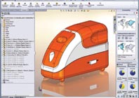
There are many concepts surrounding sustainable design and while your average designer or engineer will not yet understand some of them, others will be much more familiar. A perfect example is what’s referred to as light-weighting. The basic concept is simple: reduce the environmental impact of a product by reducing the amount of material used. This can be achieved by redesigning an existing product, by considering the environmental impact during clean sheet design or by using different materials. While we’re not going to discuss material selection at length here, the remainder we most certainly are.
Pro/Engineer’s Behavioural Modelling Extension gives you a full suite of design optimisation tools and goal seek analysis. It’s an additional bundle, but it’s worth exploring if you already have it licensed.
Light-weighting has been part of the design and engineering toolkit for decades. With material costs rising, reducing the amount of materials used has become a key economic driver on most design or engineering projects. It also saves the Earth’s valuable resources, not only in terms of the amount of material used, but in relation to the energy required to refine the raw materials or during transportation and manufacture.
Whether you’re approaching light-weighting from an economic or a sustainability angle, there are a rich set of tools out there to assist with this key part of the detailed design process. And these tools are often already part of the workhorse design system you’re already using. They can be applied at different stages of the development process – so let’s explore them in more detail.
At the point of ideation
It may sound obvious but the perfect point to identify where optimisations can be made is at the ideation and conceptualisation phase. It’s at these formative stages, before getting stuck into the detailed design, that you have the ability to consider everything from a higher level.
Is there potential to combine components into a single component that serves the same purpose? Is there an alternative structure or way of providing the same functionality you need that uses less material?
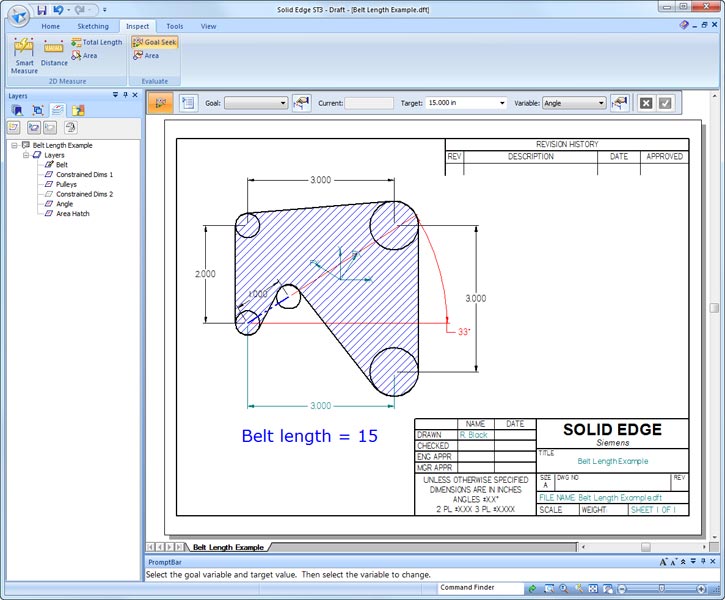
Aside from the ‘brain-crunching’, there are technologies that can help. A perfect example is Goal Seek Analysis. This begins with a basic parametric schematic layout of a design, be that a structural part, a mechanism or any other element. The parameters and their ranges are then defined along with a goal (be that a target function, weight, volume etc). The system then works out an optimal design in relation to these given conditions and this can then be fleshed it out into a 3D design.
There are a couple of entry points into Goal Seek analysis. Solid Edge has offered these tools since V20, while Inventor got them in 2010. There are also more rudimentary systems out there that target this type of process specifically – one example is GraphiCalc from Geomate (Inventbetter.com).
Simulation techniques
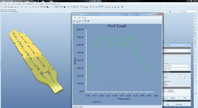
Alongside concept-level engineering and design tools, there are all manner of comprehensive simulation techniques and technologies that can be used once a design has been developed more. In relation to light-weighting, the simulation world is your proverbial oyster.
Simulation, if done correctly, can give you an excellent idea of where material can be removed from a component or how a component can be redesigned. There are dedicated optimisation routines to help with this.
All of the simulation tools built into today’s workhorse design systems provide one form of optimisation or another. These typically follow a very similar route to Goal Seek analysis except they typically work in a 3D environment, rather than with a basic sketch. The user creates a parametric model, decides on the ranges for experimentation and defines the set of goals. The system then conducts a series of experiments to find the optimum solution and presents you with the results.
As each instance or experiment requires a separate simulation, calculation times can be very long indeed. The good news is that, providing your inputs are correct, you’ll end up with a very clear understanding of what influences the performance of your product and where material can safely be removed.
Alternatives: Alongside these standard and widespread tools there are also some other simulation related techniques worth exploring. Ansys has topology optimisation tools built into Workbench which can find areas for material removal under loading conditions. Another example is based on Wolff’s Law. This defines how bones grow to ensure strength is found where it’s needed according the forces encountered.
Altair Engineering is the only company that has built this type of technology into its products. It can be found in its aerospace and automotive focussed OptiStruct system and in its mainstream Morphogenesis tools – part of solidThinking Inspired. Design inspired by nature is commonly known biomimmicry.
Conclusion
To my mind, the business case is simple. If you use less material but achieve the same required performance in your products it will save you money. In some cases it will also make your product more performance efficient. Combine this with the sustainability angle, you have lower carbon emissions and energy consumption and there’s much less environmental waste/damage. And with today’s customers in both the consumer and business-to-business world becoming more efficient and environmentally aware, it’s a win for all.
Integrating light-weighting with Life Cycle Assessment using SolidWorks Sustainability
1. Starting with a current design concept for a personal humidifier, SolidWorks Sustainability is used, in combination with the SolidWorks assembly visualisation tools, to identify components that have the greatest environmental impact. In this case, the water tank is the key contributor – so some work is needed.
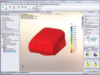
2. As this is a personal product, users are likely to place heavy objects on the flat surface of the water tank. A Factor of Safety is required of above 2.0. Simulation is run to find out the performance of this key part under typical loading. The results indicate that the current design will yield a factor of safety of 2.46, but how do you make your design more green?

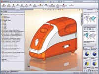
3. The ‘Find Similar Materials’ tools in SolidWorks helps you form a shortlist of alternatives, both in terms of environmental impact and mechanical properties such as tensile strength to withstand the operating conditions. A good choice looks to be Polyprop Homopolymer as it has the required properties.
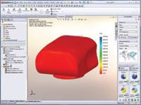
4. The environmental impacts are reduced, but re-running the FEA analysis shows that the part yields a Factor of Safety of 5.2 using the new, stronger material. This indicates that the component’s current design is over engineered, using too much material.
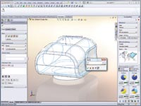
5. A quick redesign is performed that reduces the wall thickness of the component. Using less material will obviously have a larger effect on your environmental impact values, but when combined with the updated stress analysis, it is found that the component also now satisfies the Factor of Safety check (at 2.1) as well.
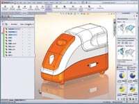
6. Returning to the assembly level model, you can now asses the environmental impact of the new design as a whole, and not just on a part level, and compare this to the original design.
Al Dean explores one of the key concepts in sustainable design and how it relates to product development.
No