Improperly constrained parts can suffer from undesired induced stresses and failures from poor fit. Joe Moak makes his DEVELOP3D debut with a guide to understanding physical constraints in product design
Part constraints are one of the most fundamental factors affecting ease of assembly, part fit, reliability, and overall product quality. Throughout my experience in both medical device and consumer product design I have seen many improperly constrained parts fail from undesired induced stresses and poor part fit. I have also seen production processes with wide, inaccurate process windows because of poor fixturing. By understanding some simple fundamentals of physics and applying a simple thought process, engineers can design robust, reliable, easy-to-assemble parts and assemblies that are less likely to create undesired induced stresses and the failures associated with poor part fit.
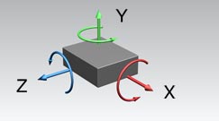
figure 1
First, I apologise to any hardcore physicists and mathematicians in the audience. I know that what follows is possibly incomplete and technically incorrect in your academic circles. That said, the aim of this article is to give non-academics a foundation upon which to build a better understanding of physical constraints in product design so I’m going to simplify the topic into something readily applicable.
Before getting into a simple example I’d like to start with some background. Any object floating in space has six degrees of freedom; translation along each of the three coordinate axes, X, Y, and Z, and rotation about each of these axes (see Figure 1). If each of these degrees of freedom is satisfied for a given component, that component is perfectly constrained. If more than one feature constrains any single degree of freedom, the component is over-constrained. If any degree of freedom is left unconstrained completely then the component is under-constrained. Over-constrained components are at risk for stress-induced failures and under-constrained components are at risk for poor fit, which can lead to any number of failures. Mechanisms are created by intentionally leaving degrees of freedom unconstrained, but that’s a topic for a different discussion. For now I’m going to focus this discussion on static part fit and assembly.
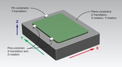
figure 2
Let’s consider constraining a simple, flat plate component. This plate can represent a circuit board going into an electronics chassis, a simplified exhaust manifold going onto an internal combustion engine, or any other plane-to-plane component attachment which is common in mechanical design.
Figure 2 shows a perfectly constrained plate component. Gravity and the plane-to-plane surface mate constrains translation in the Z-direction, rotation about the X-axis, and rotation about the Y-axis. The two pins along the left edge constrain translation along the X-axis and rotation about the Z-axis. Lastly, the pin at the back edge of the plate constrains translation along the Y-axis. This plane/line/point approach is very typical of inspection and manufacturing fixture design.
Obviously gravity won’t hold a circuit board in position or a manifold cover to an engine block. Additional assembly features and fasteners are required to create a robust mechanical attachment. We also need to consider other real-world mechanical concerns affecting part geometry such as part flexure, thermal expansion, manufacturing tolerances, water absorption, etc.
Continuing with this example I’m going to get rid of the pins and add some screws to locate the plate and lock translation in the Z-direction. Think of a screw as a localized, secure, variable-length Z-direction constraint. We can establish X-translation, Y-translation, and Z-rotation constraints by adjusting the clearance holes for the screws. Since we are trying to achieve the best alignment possible between our components a common inclination is to design all screw holes with tight fits as shown in Figure 3 over the page.
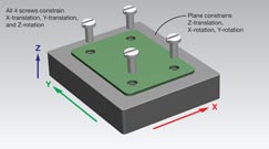
figure 3
As you can see, the plate is over-constrained. The plane-to-plane mate constrains translation in the Z-direction and rotation about the X and Y axes just as in Figure 2. The fit between the plate and screws are problematic. Each is trying to constrain the part against X and Y translation and Z-rotation. In the real world with real parts we have manufacturing tolerances, water-absorption, thermal expansion, etc. to contend with and the chances of all of our holes lining up perfectly is about zero. Supposing we can get all the holes to line up enough to sink all four screws, this assembly is at serious risk of failure due to stresses induced by interferences between the plate and screws.
Now let’s take a step back and reconsider this assembly using the “plane/line/point” approach of establishing constraints.
Figure 4 shows a much better attachment design. As in Figure 2, the plane-to-plane mate constrains translation in the Z-direction and rotation about the X and Y axes. The screw in the lower left has a tight clearance hole and locks translation in both the X and Y directions. The slot in the lower right provides clearance in the X-direction and the tight fit in the Y-direction constrains the plate in rotation about the Z-axis. The two screws in the back corners have large clearance holes and only prevent against part flexure due to movement in the Z-direction. From a mechanical-design perspective, this part is perfectly constrained. Assuming the holes and slots are properly sized to accommodate manufacturing tolerances we expect these parts to go together very easily and create a robust mechanical assembly.
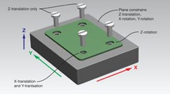
figure 4
This simple example demonstrates the thought process behind creating geometry to establish perfectly-constrained components within a mechanical assembly. There are many other ways to accomplish the attachment we discussed here using different types of locating features; pins, ledges, standoffs, shoulder-screws, snaps, rivets, etc. Deciding what types of constraints are appropriate for a specific application and how to implement them will depend on the specifics of the assembly and desired fit and function. Establishing constraints specifically to achieve functional and cosmetic goals while accommodating real-world part variations will be the subject of subsequent articles.

Joe Moak avoids undesirable stresses and failures