
When choosing a professional graphics card for SolidWorks bigger is not always better. It depends on the types of models you create, writes Greg Corke
In terms of 3D graphics, SolidWorks is one of the most advanced mid-range CAD applications out there. Its RealView technology, which enables designers to work with realistic images when modelling, was one of the first examples of real time rendering in a mainstream CAD application.
SolidWorks was also one of the first applications to feature Level of Detail (LoD) technology in its 3D graphics engine, which simplifies geometry when rotating, panning and zooming in order to maintain frame rates. And finally, it features a technology called VBOs (Vertex buffer Objects), which takes some of the load off the CPU (Central Processing Unit) and puts it onto the GPU (Graphics Processing Unit) to improve performance.

Click to find out which graphics cards clocked up the best results when working with Solidworks
In the course of this article we will look at how these different technologies affect 3D performance by testing with a variety of models, display states, and a wide range of professional graphics cards, from the entry-level right up to the high-end. Before we do this though we need to explain a few things in a bit more detail.
RealView
This uses the Shader Model 3.0 capabilities of modern professional cards to give a more realistic visualisation of real world materials. By having this enhanced visual quality, however, an additional load is placed on the graphics card, which can greatly affect performance.
The technology was introduced in SolidWorks 2007 with basic set of around 100 shaders but for 2008 the whole technology was revamped and SolidWorks took the materials and textures from its rendering add-on, PhotoWorks, and implemented them in RealView.
Some users, particularly those involved in product design, like to use RealView all the time as they find it helps to model with realistic materials. Others, perhaps those in machine design, prefer to switch it off completely as they find it detracts from the modelling task at hand. Shading can also be used to communicate other information in the design. For example, colouring all the weld faces in an assembly in blue for clarity.
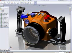
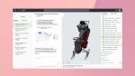
SolidWorks digital camera model features complex geometry
Large Assembly Mode
This was introduced to help prevent workstations grinding to a halt when working with sizeable models. It is automatically invoked when an assembly reaches a certain number of components. Large assembly mode automatically switches off RealView and sometimes edges, and when panning, zooming, rotating, or moving a component, decreases the Level of Detail seen in the model. Sometimes this can mean quite complex geometry is reduced to simple boxes.
Large assembly mode is optional. Some users prefer working with it on because they don’t like experiencing jerky graphics, which can happen with particularly large models. Others prefer not to use it because they want to see the full details of their designs at all times. Settings can be fine tuned for a balance between quality and performance.
Vertex Buffer Objects (VBO)
These allow 3D geometry to be loaded, stored and processed on the graphics card. When displaying a model, geometry data doesn’t have to be moved back and forth over the PCI Express bus, as has traditionally been the case. This helps minimise the instances when the GPU has to wait for the CPU (as it is often tied up with other tasks) and as a result can boost real-time 3D performance.
In SolidWorks, VBOs are built for every individual body in the model. Complex bodies that are made up of many faces benefit much more from VBOs than simple bodies with few faces. To put this in perspective, when VBOs are turned off in the relatively complex digital camera model (see Figure 1) 3D performance is about 2x slower. However, with a huge model made entirely out of cubes, VBOs would provide no benefit.
Those who use RealView on models featuring complex geometry are likely to benefit more from powerful graphics cards than those with simple geometric models
TEST process and results analysis
Graphics performance can be measured in many ways, such as the time taken to generate a scenegraph or to switch between modelling windows. However, the most common method is to test for frame rate. Generally speaking 20-30 FPS is preferable for smooth model manipulation, though some find they can work with 10-20 FPS. Anything less and models are generally too jerky and it’s hard to move them accurately on screen. To capture frame rate we used a macro called Spin500 that rotates a model and records an average Frames Per Second (FPS). It should be noted that this is likely to record slower frame rates than in the real world as it bypasses some of SolidWorks’ optimisations.
We tested each graphics card in SolidWorks 2009 with the latest certified drivers using a range of models with RealView switched on/off. Large Assembly mode was switched off and the display mode was set to shaded plus edges.
A single workstation was used for testing and this featured a Core i7 940 (2.93GHz) processor, 6GB RAM and Windows XP X64 Edition. The machine was provided by Workstation Specialists (previously known as CAD2), the only independent workstation manufacturer to have been awarded SolidWorks Solution partner status (www.workstationspecialists.com).
Our first model, the digital camera assembly (see Figure 1),is made up of relatively complex geometry and the more powerful graphics cards showed real benefit when RealView was turned on. This is because the model makes good use of complex VBOs so the full power of the card is able to be harnessed. With RealView turned off, the frame rate rose considerably, but there was very little performance difference between the cards. This is because far less load is placed on them and most can deal easily with this level of computation.
For our second test model, the radio-controlled car (see Figure 2), there was little additional benefit from the higher end cards with both respective families of FirePro and Quadro FX cards delivering similar results. The logical explanation for this is that the CPU becomes the bottleneck meaning SolidWorks can’t make use of the additional power of the higher-end cards. To increase graphics performance a CPU with a greater GHz would be required.
AMD’s ATI FirePro V3700 was the anomaly in this test with its performance significantly slower with RealView switched on. This suggests that the graphics card is the bottleneck here and not the CPU. However, once the load on the card was lightened by turning off RealView, the performance of the V3700 was as good as the other cards.
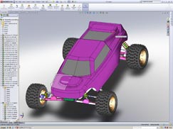
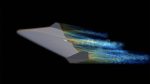
SolidWorks radio controlled car model features relatively simple geometry
We also tested with other assemblies. Most benefitted from the more powerful cards, but to a lesser extent than with the camera model. Some extremely large models supplied by RJ Herbert, a manufacturer of handling equipment, were CPU limited with no perceivable benefit from the more powerful graphics cards and delivering poor frame rates. The geometry of these models was not particularly complex, but the number of components was huge.
Putting these results in perspective, and simplifying things considerably, frame rate is governed by two factors – the number of components and the number of triangles (a rough measure of the complexity of the geometry). The more components there are, the more complex the assembly tree, and a greater load is put on the CPU. Models with highly complex assembly structures are likely to become CPU limited (the CPU is the bottleneck).
The more triangles there are, the bigger the load on the GPU. If you have a model with lots of complex surfaces/components, each having a huge number of triangles, the GPU may become the bottleneck before the CPU and hence users will benefit from more powerful graphics cards.
Closing thoughts
Choosing a graphics card for SolidWorks is not a straightforward process. It depends entirely on the types of models you work with and how you wish to view them.
In all scenarios, start off with the fastest GHz CPU you can afford. This will boost 3D performance across the board. Next up you need to consider the types of models you work with. Those who use RealView on models featuring complex geometry with lots of faces are likely to benefit more from powerful graphics cards than those with simple geometric models.
In terms of specific cards, at the entry-level, the FirePro V3750 offers excellent price/performance, though if you work with particularly large assemblies which use more than 256MB frame buffer memory (see box out), the FirePro V5700 or Quadro FX 1800 may be better options. For GPU-bottlenecked models, and where budgets allow, the Quadro FX 3800 looks to be an excellent choice.
When models reach a certain size/complexity, no matter how much graphics power you throw at them, it’s impossible to achieve desirable frame rates. In these instances it is essential to work in Large Assembly mode with Level of Detail degrading geometry to maintain frame rates.
www.solidworks.com
www.nvidia.com
www.ati.amd.com
Greg Corke discovers size isn’t everything. It’s what you do with it.
In terms of 3D graphics, SolidWorks is one of the most advanced mid-range CAD applications out there. Its RealView technology, which enables designers to work with realistic images when modelling, was one of the first examples of real time rendering in a mainstream CAD application.
SolidWorks was also one of the first applications to feature Level of Detail (LoD) technology in its 3D graphics engine, which simplifies geometry when rotating, panning and zooming in order to maintain frame rates. And finally, it features a technology called VBOs (Vertex buffer Objects), which takes some of the load off the CPU (Central Processing Unit) and puts it onto the GPU (Graphics Processing Unit) to improve performance.

Click to find out which graphics cards clocked up the best results when working with Solidworks
In the course of this article we will look at how these different technologies affect 3D performance by testing with a variety of models, display states, and a wide range of professional graphics cards, from the entry-level right up to the high-end. Before we do this though we need to explain a few things in a bit more detail.
RealView
This uses the Shader Model 3.0 capabilities of modern professional cards to give a more realistic visualisation of real world materials. By having this enhanced visual quality, however, an additional load is placed on the graphics card, which can greatly affect performance.
The technology was introduced in SolidWorks 2007 with basic set of around 100 shaders but for 2008 the whole technology was revamped and SolidWorks took the materials and textures from its rendering add-on, PhotoWorks, and implemented them in RealView.
Some users, particularly those involved in product design, like to use RealView all the time as they find it helps to model with realistic materials. Others, perhaps those in machine design, prefer to switch it off completely as they find it detracts from the modelling task at hand. Shading can also be used to communicate other information in the design. For example, colouring all the weld faces in an assembly in blue for clarity.
SolidWorks digital camera model features complex geometry
Large Assembly Mode
This was introduced to help prevent workstations grinding to a halt when working with sizeable models. It is automatically invoked when an assembly reaches a certain number of components. Large assembly mode automatically switches off RealView and sometimes edges, and when panning, zooming, rotating, or moving a component, decreases the Level of Detail seen in the model. Sometimes this can mean quite complex geometry is reduced to simple boxes.
Large assembly mode is optional. Some users prefer working with it on because they don’t like experiencing jerky graphics, which can happen with particularly large models. Others prefer not to use it because they want to see the full details of their designs at all times. Settings can be fine tuned for a balance between quality and performance.
Vertex Buffer Objects (VBO)
These allow 3D geometry to be loaded, stored and processed on the graphics card. When displaying a model, geometry data doesn’t have to be moved back and forth over the PCI Express bus, as has traditionally been the case. This helps minimise the instances when the GPU has to wait for the CPU (as it is often tied up with other tasks) and as a result can boost real-time 3D performance.
In SolidWorks, VBOs are built for every individual body in the model. Complex bodies that are made up of many faces benefit much more from VBOs than simple bodies with few faces. To put this in perspective, when VBOs are turned off in the relatively complex digital camera model (see Figure 1) 3D performance is about 2x slower. However, with a huge model made entirely out of cubes, VBOs would provide no benefit.
Those who use RealView on models featuring complex geometry are likely to benefit more from powerful graphics cards than those with simple geometric models
TEST process and results analysis
Graphics performance can be measured in many ways, such as the time taken to generate a scenegraph or to switch between modelling windows. However, the most common method is to test for frame rate. Generally speaking 20-30 FPS is preferable for smooth model manipulation, though some find they can work with 10-20 FPS. Anything less and models are generally too jerky and it’s hard to move them accurately on screen. To capture frame rate we used a macro called Spin500 that rotates a model and records an average Frames Per Second (FPS). It should be noted that this is likely to record slower frame rates than in the real world as it bypasses some of SolidWorks’ optimisations.
We tested each graphics card in SolidWorks 2009 with the latest certified drivers using a range of models with RealView switched on/off. Large Assembly mode was switched off and the display mode was set to shaded plus edges.
A single workstation was used for testing and this featured a Core i7 940 (2.93GHz) processor, 6GB RAM and Windows XP X64 Edition. The machine was provided by Workstation Specialists (previously known as CAD2), the only independent workstation manufacturer to have been awarded SolidWorks Solution partner status.
Our first model, the digital camera assembly (see Figure 1),is made up of relatively complex geometry and the more powerful graphics cards showed real benefit when RealView was turned on. This is because the model makes good use of complex VBOs so the full power of the card is able to be harnessed. With RealView turned off, the frame rate rose considerably, but there was very little performance difference between the cards. This is because far less load is placed on them and most can deal easily with this level of computation.
For our second test model, the radio-controlled car (see Figure 2), there was little additional benefit from the higher end cards with both respective families of FirePro and Quadro FX cards delivering similar results. The logical explanation for this is that the CPU becomes the bottleneck meaning SolidWorks can’t make use of the additional power of the higher-end cards. To increase graphics performance a CPU with a greater GHz would be required.
AMD’s ATI FirePro V3700 was the anomaly in this test with its performance significantly slower with RealView switched on. This suggests that the graphics card is the bottleneck here and not the CPU. However, once the load on the card was lightened by turning off RealView, the performance of the V3700 was as good as the other cards.
SolidWorks radio controlled car model features relatively simple geometry
We also tested with other assemblies. Most benefitted from the more powerful cards, but to a lesser extent than with the camera model. Some extremely large models supplied by RJ Herbert, a manufacturer of handling equipment, were CPU limited with no perceivable benefit from the more powerful graphics cards and delivering poor frame rates. The geometry of these models was not particularly complex, but the number of components was huge.
Putting these results in perspective, and simplifying things considerably, frame rate is governed by two factors – the number of components and the number of triangles (a rough measure of the complexity of the geometry). The more components there are, the more complex the assembly tree, and a greater load is put on the CPU. Models with highly complex assembly structures are likely to become CPU limited (the CPU is the bottleneck).
The more triangles there are, the bigger the load on the GPU. If you have a model with lots of complex surfaces/components, each having a huge number of triangles, the GPU may become the bottleneck before the CPU and hence users will benefit from more powerful graphics cards.
Closing thoughts
Choosing a graphics card for SolidWorks is not a straightforward process. It depends entirely on the types of models you work with and how you wish to view them.
In all scenarios, start off with the fastest GHz CPU you can afford. This will boost 3D performance across the board. Next up you need to consider the types of models you work with. Those who use RealView on models featuring complex geometry with lots of faces are likely to benefit more from powerful graphics cards than those with simple geometric models.
In terms of specific cards, at the entry-level, the FirePro V3750 offers excellent price/performance, though if you work with particularly large assemblies which use more than 256MB frame buffer memory (see box out), the FirePro V5700 or Quadro FX 1800 may be better options. For GPU-bottlenecked models, and where budgets allow, the Quadro FX 3800 looks to be an excellent choice.
When models reach a certain size/complexity, no matter how much graphics power you throw at them, it’s impossible to achieve desirable frame rates. In these instances it is essential to work in Large Assembly mode with Level of Detail degrading geometry to maintain frame rates.
www.solidworks.com
www.nvidia.com
www.ati.amd.com


