

The Bugatti Chiron is a €2.5 million net supercar unlike anything else on the road today
In the world of supercars, one name is perhaps seen as the pinnacle of the fast, the beautiful and the very expensive.
Bugatti has, in various forms, been at the forefront of both automobile design and performance since the 1900s.
In its current incarnation, rescued from obscurity by Volkswagen AG in the late 1990s, both the Veyron and its successor, the Chiron, are seen as the supercars to end all supercars.
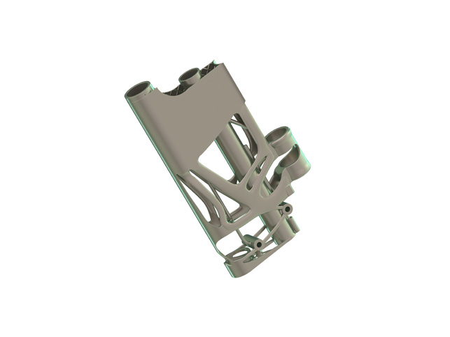
The Bugatti rear wing system demo assembly on show at Hanover Fair
At the recent Hanover Fair, Bugatti unveiled work it has been doing to solve a particular design challenge found in its Chiron supercar.
The project revolved around the challenge associated with keeping the supercar on the road at over 400 km/h – impressive, considering a 747’s take-off speed is 280 km/h.
This is only possible with the Chiron’s active aerodynamics and one of the key components of this is the rear wing system.
Bugatti was looking to strip some serious weight out of the existing assembly which, on the basis of previous simulation and production technologies, actually offers a perfect stiffness and strength-to-weight ratio – at the end, it was possible to reduce the weight by 53% or 5.4kg.
To achieve its ambitious targets, Bugatti worked with Siemens PLM to test out the possibilities of the vendor’s complete software solutions for simulation, calculation, construction and machine controlling in the fields of metal and carbon fibre.
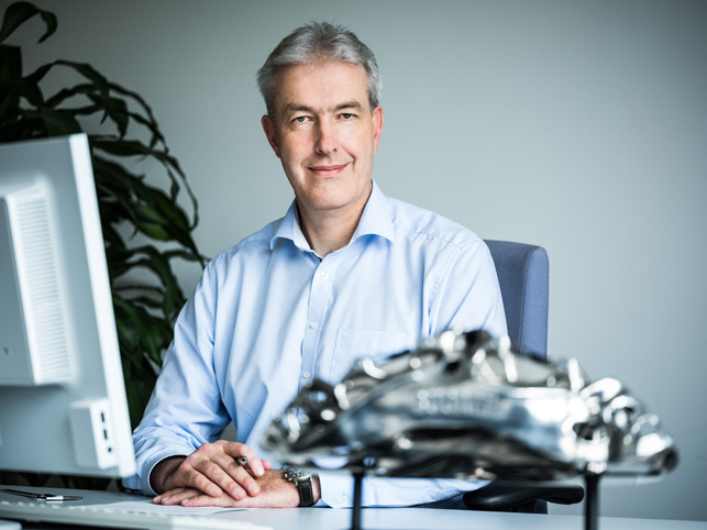
Frank Götzke, Head of New Technologies at Bugatti Automobiles S.A.S
To learn more, we spoke to Head of New Technologies Frank Götzke who, alongside one of his co-workers Anna Populoh, the project leader, carried out the project.
D3D: Could you provide us with the background to how this project came to be? Was it driven by a specific requirement or were you looking for a set of components with which to experiment with generative design and additive manufacturing technologies?
Frank Götzke: We’ve done a lot of different 3D printing projects in the past but our problem was always that we could not find a way to complete the entire process from simulation and calculation, through 3D printing and heat treatment itself to milling and finishing at the end in one closed software environment.
This resulted in a loss of precision and much more time and work was needed due to multiple data conversions. It was clear for us that this could not be the right way to work in the future.
After talking about that at conferences, Siemens approached us and offered us an opportunity to test their software environment in a joint project. The rest is history.
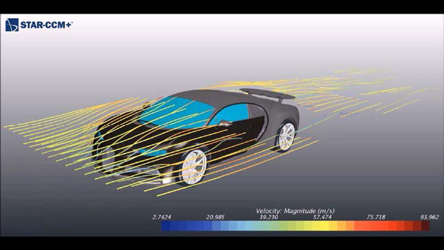
The process begins with a digital twin of the Chiron in a digital wind tunnel, replicating real-world driving conditions
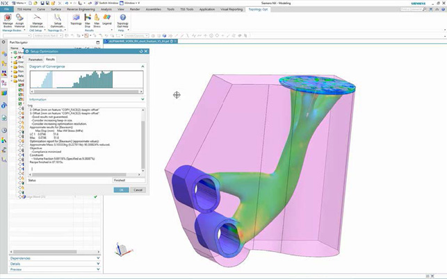
Siemens NX’s topology optimisation tools are used to generate new and novel forms according to functional requirements
D3D: How did you decide which parts were most suitable for redesign for additive?
FG: If your work is driven by performance, there is a rule of thumb: always choose the lightest and stiffest material possible.
This is carbon fibre for parts that have to function in a location in the car that is not exposed to continuous working temperatures of more than 240°C.
Where the temperature may exceed 240°C, you should use metal parts. But if you have to insert many metal parts into a carbon fibre part or to screw or bolt moveable components to it, then it makes more sense to use 3D printed titanium parts right from the start.
That is why the best solution for the Chiron’s rear wing system would be to use carbon fibre for the two guiding tubes and the rear coupling rod for the best technical performance, strength-weight ratio and stiffness-weight ratio.
All the other parts – the two lower side mounting brackets, the traversing unit itself with its two sensors, the two-part wing mounting bracket and the wing adjustment slider – would be made out of 3D-printed titanium, because they involve a lot of screwing and bolting points.
In view of these points and the fact that the rear wing is very important for the car’s aerodynamic behaviour, this system gave us the ideal opportunity to test all the capabilities of the Siemens software environment.
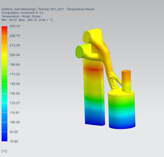
Siemens Additive Toolset brings simulation of build processes for metal parts
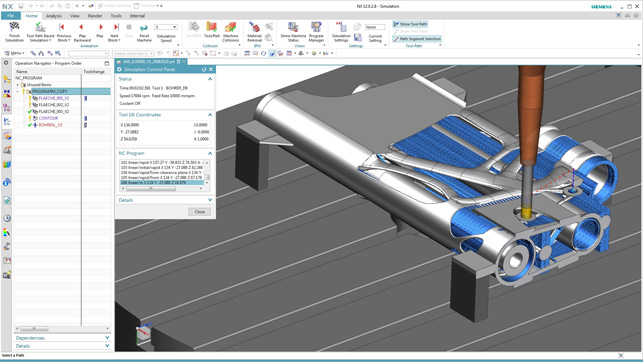
Post-build CNC machining and simulation using NX
D3D: In terms of capturing loading and constraint conditions, how was this accomplished?
FG: It all starts with a simulation in a virtual wind tunnel, a so-called CFD simulation. For that purpose, we used a digital twin of the complete Chiron with all its outer and inner surfaces on a simulated road. The second step was to measure the hydraulic pressure in the cylinders for traversing and tilting the wing and the elastic deflection of the rear coupling rods in the real car, while driving on our proving ground in Ehra-Lessien, Germany.
If the loads from these measurements in the field are identical with the simulation results, you can start the third step: the topology optimisation process for the different parts of the system. If not, you have to adapt your virtual car and environment and start over with your tests.
D3D: Could you walk us through the process in terms of designing these components?
FG: We had the rear wing system with all its functions, for example the break flap functionality, in our cars from the first Veyron onwards. So this time we did not need to develop a rear wing system, but to adapt new simulation and production technologies to the given parts.
We knew the stiffness that had to be reached, we knew the forces to be handled, the installation space was completely defined, the hydraulic pressure was known, and so on.
To test the Siemens software environment, we built a new digital twin of our car and we carried out many new CFD simulations to compare these processes and their results with the processes and results from the development of the Chiron.
We optimised the topology, defining the maximum space, using the forces resulting from the CFD simulation, bringing in the stiffnesses needed etcetera, without any data conversion directly in a closed Siemens software environment. Normally, we would use many different software products; this time, just one was needed.
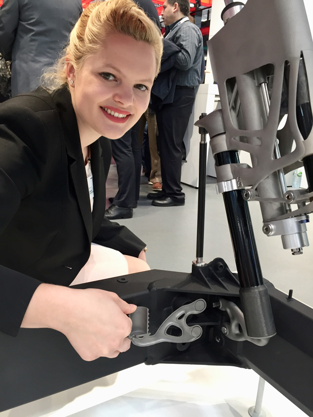
Anna Populoh, project leader and technical designer of the 3D-printed titanium parts, showing off the internal structure of the lower supports
D3D: It’s interesting that you have two possible approaches in this project. You can topology-optimise a part and use it directly. Alternatively, you can use the topology-optimised geometry as inspiration and then re-design the part using normal modelling and sub-divisional techniques. Do you have a feeling for which approach is most suitable and when? How do you decide?
FG: The objective of our project with Siemens was to find a way to use the structure optimised by the topology for the printing process in a closed software environment and not to use it only as an inspiration; that works excellently – and that is one of the most important conclusions of the project.
D3D: Some portions of the smaller bracket designs have been hollowed to take advantage of improved “section modulus against bending” characteristics. Is this a technique that you see being used more widely in the future to find the sweet spot between strength and weight for printed parts?
FG: You are absolutely right – if there is enough space to build a tube instead of a solid rod, hollow structures with the same material cross sectional area are always stiffer. But it was tricky to get such hollow structures out of the simulation and topology optimisation processes and it was even trickier to print them. Now we will use the new findings regarding simulation and printing for all our future 3D printing projects.
D3D: The assembly is stated to be 50% lighter. How does the proportion of that weight saving work out between the use of additively manufactured parts and the use of the carbon fibre replacing previously metallic parts?
FG: Looking back at all the parts that we have designed for 3D printing in the past, one can say that the replacement of a metal part with a 3D printed metal part can normally lead to a weight reduction of more than 40% while keeping the same stiffness.
In contrast, the replacement of a metal part by a carbon fibre part on the basis of high modulus/high strength fibres and tailored fibre placement can lead to a weight reduction of around 70%.
Bugatti used the results of topology optimisation directly as the basis for main parts
D3D: How much is cost an issue for an organisation like Bugatti. Is it a factor in the decisions made here or was this project purely about performance?
FG: On the one hand, there is no question that Bugatti is about ultimate performance: the best technology, the best styling, the best quality and the best customer service one can get with a car. On the other hand, Bugatti is a company that has to achieve business success like any other company.
D3D: Can you elaborate on the importance of simulation during the various steps in the design-to-print process for this project?
FG: Without simulation, it is impossible to make usable 3D printed parts. It starts with the virtual wind tunnel, then continues with the topology optimisation, followed by the process and heat treatment simulation, and ends with the milling simulation to find the best way for finishing.
D3D: If you had to do the project again, what would you change?
FG: Nothing. We had the right materials, the right production processes, the right machines, the right software and, last but not least, the right partners.
D3D: Will this set of components be made available on the Chiron in production?
FG: No, this was not the intention. From the beginning it was our plan to test the Siemens software environment, nothing else. So, together with our partners from Siemens, we have found out a lot of things that can be used in future projects.
D3D: Will the lessons you have learned be share in the wider VW Group?
FG: Bugatti is the Group’s Laboratory for Applied Future Technologies. So whatever we are doing in the field of new and future technologies will be shared with everyone who is interested inside the Volkswagen Group.
D3D: If you had to summarise how you see Bugatti using this type of workflow in the future, what sort of prediction might you make?
FG: The world’s first 3D-printed functional metal part in a production car can be found in our Chiron. For the future, I see a lot of more parts that could be made by 3D printing. But I am absolutely convinced that the use of carbon fibre will remain key for us and that technologies like 5-axis milling and forging will also continue to be important.
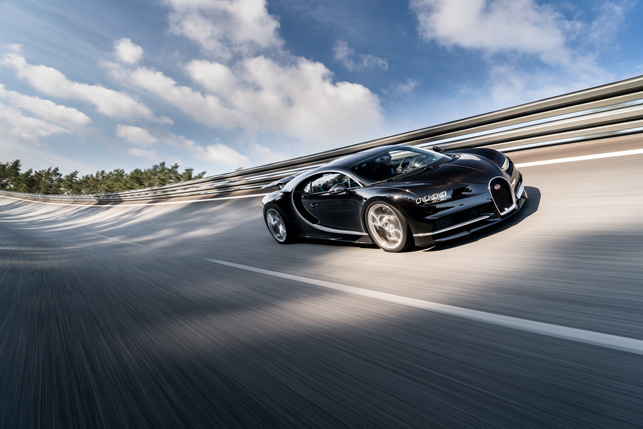
The Chiron is limited to 500 units and is capable of 0 to 400 km/h in 32.6 seconds
D3D: If you had advice for another design or engineering team looking to use this type of technology, what would it be? Where should they start?
FG: Everyone should always keep in mind that 3D printing is an extremely cost-intensive and very slow-production technology. So it makes no sense to start with parts for a medium-sized series. And even in small-scale, the cost means that the process is normally only viable for the prototype stage.
First of all, you will have to find parts that cannot be made with the usual production technologies. If you need parts that need to have oil or water ducts inside, for example, and if these ducts are intertwined and twisting, so that you cannot drill or mill them, and it is too complicated to make a precision cast tooling, then you have a good starting point to take 3D printing into consideration.
D3D: What surprised you during the process that you can share with our readers?
FG: As I started working on 3D printing in 2010, a new project now has no major surprises for me anymore.
Sometimes, it is a surprise that a lot of people seem to think that this technology is ready to be used for medium and large-scale production and that you only need a 3D printer to be an expert.
It has to be clear that you need very good, proven partners with a great deal of experience and special know how in the field of 3D printing to produce a properly functioning part.
D3D: How do you see additive manufacturing and composite fibre parts playing a role in the future of the automotive industry?
FG: It is essential to reduce the cycle times in order to use these technologies for medium- or large-scale production. At the moment, metal 3D printing and carbon fibre technologies are light years away from this.
If you look at e-mobility, for instance, it will be important to develop structures that are both light and rigid to make up for the heavy batteries.
I am confident that metal 3D printing will continue to develop in the future. There are many ideas and concepts and we have to work on them. In the field of carbon fibre technologies you can see that progress has been made since we started in 2001.
The parts have become lighter, stiffer and more resistant to higher temperatures. Production has become faster and more cost-efficient. And yet, it takes many more steps and we have to work on defining the right direction for further developments.

How additive manufacturing technologies are accelerating design at Bugatti Automobiles
Default


