They say four wheels move the body but two wheels move the soul – they also say that most motorcycle problems are caused by the nut that connects the handlebars to the saddle, but that’s another story.
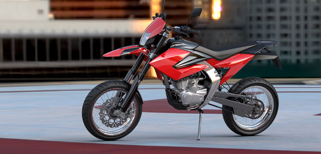
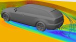
Scene set-up rendering of the Dafra 150 off-road
The guys who run the motorcycle industry are a canny lot, fully aware of the folklore that develops around their brands, and they rightly promote and enthusiastically extol these intangible virtues as heavily as they do the vital numbers like power outputs or chassis dimensions.
What they’re less forthcoming with are the identities of the consultant designers who help them achieve these things.
So against the backdrop of anonymity generally demanded by an industry producing largely aspirational vehicles, it’s rather refreshing to be able to talk about actual examples of work – and when this coincides with the application of a design methodology that significantly improves quality and shortens new model introduction lead times, it’s definitely worth mentioning in despatches.
For example, our designs for Brazilian outfit Dafra Motos put them on the fast track to production cutting the traditional development time by at least a third and allowing simultaneous engineering activities to take place far sooner in the programme.
At the heart of this methodology is the CAD model data, which is developed soon after the initial styling drawings and packaging studies have been signed off.
Designers and engineers work together to create ‘tool ready’ 3D ‘A surface’ data in a virtual CAD environment, and this all takes place before any physical modelmaking is done – in other words, there is no physical clay model stage.
Unlike the traditional processes, the data is ‘actual’ rather than approximate having been built to accommodate the required packaging, ergonomics and dynamic specification from the very start.
This master data is then used downstream to cut physical surfaces or build rapid prototype parts for verification and assessment of the design on a physical buck.
Any minor modifications are subsequently done entirely in CAD prior to handover of the data for ‘B surface’ generation and toolmaking. The process also applies equally to the chassis and cycle parts, although these do benefit from a first pass physical mock-up stage.
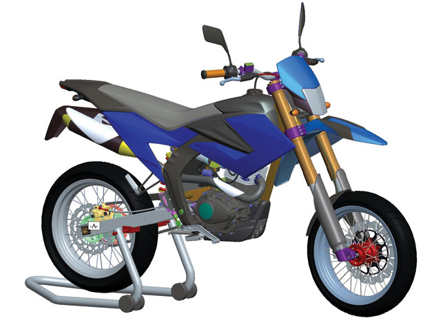
The virtual design process
CAD modelling revolves around a skeleton underlay – a set of curves placing the fundamental packaging geometry and the creative designer’s intent together in a single model.
More often than not this initial work is created in Alias, which has the flexibility and speed to allow for free sketching.
The frame subassembly is then brought into the assembly along with the engineering package, which contains the engine and power-train, cooling system, induction system, the electrics and the dynamic envelope of steering, suspension and ground clearances.
Any non-fixed parts such as the front suspension and yokes, and the rear swing arm subassembly are assembled to features on the skeleton that are driven by dimensions, allowing combinations of full-lock/bump etc to be accommodated.
This design process means that changes can propagate through to all downstream deliverables, reducing the need to re-work ‘B surface’ details and engineering schemes following design modifications.
One example could be the ‘shrinking’ of a cockpit around a headlight package or the ‘narrowing’ of side panels to accommodate a late change request by the packaging engineers – perhaps even after a panel fixing scheme has been modelled into the ‘B surface’.
Surfaces are analysed to ensure they adhere to downstream engineering and tooling requirements with respect to draft angles and undercuts at the time of creation, eliminating the need for expensive re-working.

Reference points and dependencies can be specified between neighbouring panels or frame components, which allows design changes to propagate between them – very useful in ensuring that panel gaps remain constant!
As the assembly is always up-to-date with the current build status of body panels and mechanical components, it means the entire design team can be onboard and aware – any potential clearance/ interference issues will be highlighted and addressed at an early stage.
This is particularly helpful when the design and development teams are scattered around the globe.
There will always be those who prefer to have a physical clay model to chop and change, scan and re-scan, but with a comprehensive human factors database and a complete chassis dynamics model embedded in the assembly, virtual ‘design engineering’ is the way forward.
renfrewgroup.com
Design that eliminates the need for physical clay models
Default