The last few years have seen Inventor take huge strides, both in terms of the user experience and the sheer quantity of technology that has been added to it from motion simulation and rules-based design to FEA and mould design.
With all that’s happening within and around the product, 2011 is perhaps one of the biggest releases in quite a few years. Lets take a look at the highlights that are applicable to the majority of users and then look at some of the more niche areas of the system.

Mini Toolbars bring context sensitive options directly into the modelling interface. They adapt to both the current operation and the current selection
User experience
Inventor 2010 saw the introduction of the Microsoft Ribbon, which presented the software’s multitude of commands and options in a logical manner. For 2011, the user interface doesn’t change a great deal except it now incorporates mini-toolbars, which pop up on the model and present the most common options.
Each toolbar is highly context sensitive: click a feature and you can edit the feature or the sketch; click an edge and you can add a chamfer or a fillet; click a plane or a face and you can create a sketch. Add to this, new in-operation controls with added flexibility in terms of asymmetric feature creation and the whole environment becomes even more productive, for both new and existing users.
Asymmetric feature creation makes life much easier, allowing users to build more complex parts with fewer features
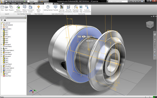
Inventor’s real time visualisation engine has also been reworked. Shadows can now be added (both on the part and on the floor) plus reflections with a range of image-based lighting environments. These use the technology found in Autodesk’s Showcase visualisation product to great effect, allowing users to work in a very visually-rich environment.
This is perfect for both everyday work and design presentations. To maximise any investment made in visualisation, all of the materials, lighting set-up and environments are fully compatible with other visualisation products in the Autodesk product range, including Showcase and 3ds Max.
If there’s one downside to the new visualisation environment it’s that users can’t apply their own HDR images. The majority of environments that are provided with the system are most suited for large-scale products, including factory floor, warehouse, and roads, but there is very little for those working on smaller scale products, such as consumer electronics. It would have been good to include some photo-shoot style environments to suit those types of products.
Assemblies
Assembly modelling sees a couple of key updates for this release. In terms of assembly creation, there are two key updates. Firstly, the new constraint limit allows users to specify a specific range of motions for a component’s movement or rotation, defined as a maximum, minimum and a resting position value.
The new real time visualisation tools present models in a photorealistic guise with more accurate lighting, shadows and reflections
This will be hugely useful for those developing mechanisms, particularly within a machinery context, as no physical contact is required. It’s perfect for specifying known limits or requirements and then using the digital design tools to work on the unknowns and flesh them out.
A tool that is likely to be applicable to most users is the new Assemble command, which can be used to quickly snap together parts, based on a selection. It can be invoked from the menu or is made available as soon as a component is placed within an assembly.
For the majority of assembly constructions, the Assemble command saves a lot of time, meaning users don’t have to place multiple constraints. Starting with the reference geometry (e.g. a shaft on a bolt) the user then selects the geometry to which it mates (e.g. a hole) and the system does the rest. At present, it works with Mate, Flush, Directed Angle, Tangent, Insert, and UCS constraints.
The final update for general assemblies is the new changes to shrink-wrap, which allows you to protect intellectual property by masking geometry or internal details when working with clients and suppliers. The tools were introduced in 2010, but have been extended to enable the creation of multi-body shrink-wraps, which means assemblies can still be ‘active’, but the protection remains in place.
Frame design & simulation
Over the past few releases, a lot of effort has gone into making frame design much easier. This now uses a combination of an extensive standard section library, some nifty tools that build the skeleton for the frame, and some first class finishing tools to create the mitres, joints and welding conditions.
To extend the reach of this tool into the realms of simulation, the 2011 release allows users to take the frame set and conduct both structural and modal analysis on it. The system applies a technique common to the FEA world and uses a simplified representation of the frame built using intelligent beam elements, which contain cross section information.
The user simply defines the direction for gravity, where it’s fixed, any loads, forces and moments acting on the frame, and then runs the simulation. This provides a full breakdown on the resultant performance of that frame, identifying stress concentrations and deformations on a per beam basis as well as natural frequency information. From the user’s perspective it gives a lot of information on which to base redesigns.
Reports can be generated that break things down to quite an impressive level of detail. The system can also export to RTD, the native format for Autodesk’s Robot Structural Analysis Professional application, a dedicated analysis tool for structural engineers. For those using RSA, if it’s loaded on the same machine as Inventor, there are additional tools to transfer data between the two applications.
Extending Inventor
Alongside the core updates, each Inventor cycle sees work done on the add-on or ‘Suite’ products also available, which includes Simulation and Tooling.
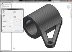
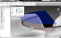
New STL output options allow uers to build rapid prototypes in a more flexible manner. Previously Inventor exported every part in an assembly into a single STL file, making life difficult for those running the 3D printing machines
Simulation has been a key focus for Autodesk for some time and the technology it has acquired over the last few years is now starting to proliferate into the Inventor Simulation Suite, with all manner of new tools coming on stream.
As machinery design is one of Inventor’s key user groups, the new Frame Analysis tool is certain to be welcomed with open arms. It allows users to test the response of frame models to both gravity as well as other loading conditions and discover where stress concentration is.
While Inventor has a huge range of modelling capabilities, it’s fair to say it struggles a little with the creation and fine tuning of complex freeform shapes. This is a common problem with most mainstream modelling applications.
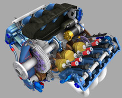
Of course, these are exactly the types of forms that the Alias tools are perfectly suited for, hence the introduction of Alias Design for Inventor. This add on product sees a set of tools built directly within Inventor that allow the user to create complex forms in a very freeform manner, using edges and direct modelling operation.
The starting point is a solid model, whose edges and faces are then pushed, pulled and manipulated into the required shape. This ‘freeform’ model is stored within the Inventor model history as an “Alias Feature” and users can then use the power of Inventor to take that shape into the engineering process to add design for manufacture and assembly details as required.
Conclusion
With Inventor 2011 Autodesk is continuing to flesh out its Digital Prototyping concept with both core modelling updates and extensions of the system into complementary areas. With additional depth of functionality both upstream (in terms of concept design) and downstream (in terms of simulation and tooling) Autodesk is really starting to put together a very impressive offering for product development.
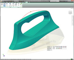
The new Alias Design for Inventor tool brings freeform modelling tools to Inventor for complex shape design from the Alias world
For me, the introduction of Alias Design for Inventor is a very important move as it gives Inventor extremely powerful freeform modelling capabilities. The downside of Alias Design for Inventor is that users need to acquire a full license of Alias Design to use it – which is around the £4,000 mark. To my mind, it would have been better integrated into Inventor proper and perhaps as a cost option, but buying a whole license of software that it most unlikely to get used by most users seems a little wasteful.
That said, to get equivalent tools in other systems (I’m thinking the ISDX module in Pro/Engineer), you’d be looking at a similar cost and with Autodesk’s approach you also get hold of a full seat of Alias, which is more than worth the money.
Alongside this, there’s a huge range of updates to the tools that surround Inventor, whether that’s Moldflow, Algor or the Simulation tools and we’ll be writing about these in coming months. Inventor, in its various Suites, represents huge value for money whichever bundle is most appropriate for your workflow and process and there’s certainly plenty to sink your teeth into.
http://www.autodesk.co.uk
| Product | Inventor 2011 |
|---|---|
| Company name | Autodesk |
| Price | Price on application |