As long time readers of DEVELOP3D will know, Delcam is a specialist in manufacturing software.
Its roots lie in the world of mould and die design and production, but during the past five years the UK-based vendor has expanded its capabilities and the industries it serves within its ever growing Power Solutions product suite.
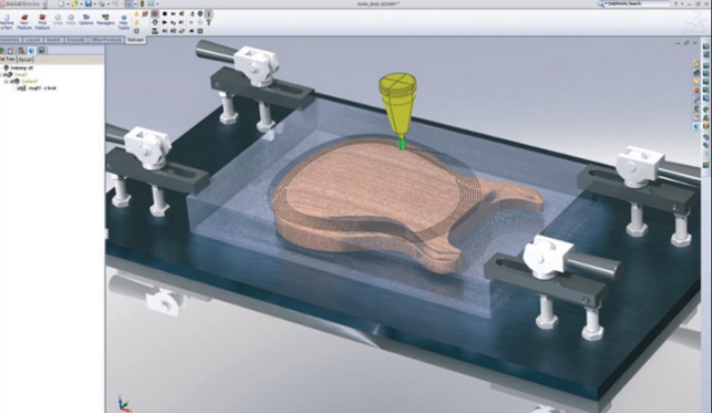
Delcam for SolidWorks lets you use all of the bells and whistles for graphic display to assist with visualising your toolpaths
During this period Delcam has mastered the art of cross transference of technology. Updates and capabilities added to one of its solutions, such as PowerShape for complex modelling, will eventually appear in its CAM systems and vice versa.
This happens across all of its tools where applicable and has also helped it develop new industry specific tools to help cater for new markets.
To this backdrop, it was with some surprise that in 2009 the company announced Delcam for SolidWorks (DFS), its integrated CAM system for SolidWorks. This was the first time that Delcam had used its knowledge and technological know-how from products like PowerMill and FeatureCAM and built them directly into another 3D design tool.
The 2011 version of DFS has been awarded Certified Gold Product Status by Dassault Systèmes SolidWorks Corp. This award confirms both the integration of the system with SolidWorks and the overall high performance when creating toolpaths from SolidWorks models.
It also means that the DFS system is fully integrated into the SolidWorks user interface. Everything runs in a single window with a new toolbar, a panel in the Property Manager to the left and another in the Task Pane, which reflects the toolbar. But it’s not just about the user interface as true integration is more than skin deep.
So, with that in mind, let’s explore how it works and what it can do.
Integration
Integration means different things to different people. CAD integration doesn’t necessarily mean that the third party software works within the same user interface as the CAD application.
However, many users are after that truly “same window, same look and feel” way of working and this is exactly what Delcam has achieved with DFS.
One of the fundamental things about DFS is that it doesn’t allow users to work with part data directly. Instead, to start a part programming job, the part needs to be placed within an assembly file.
This might seem counter intuitive, but it offers many advantages. Firstly, DFS uses the assembly file to store all of the defined machining information such as tool-paths, operations, cutter lists and NC code.
All of these are stored within a single assembly file that also references the part geometry and any stock models used. It makes things more intelligent and for those working in a PDM/PLM environment it means that he information can be managed without too many hassles.
This is because data is already in a controllable form, rather than having to manage it from disparate sources such as text files and cutter lists.
Part set-up
To begin the set up process, a part is added to the assembly file.
The next step is to determine the position of the part in terms of orientation to the base coordinate system. Following this the zero level for the Z Axis and the required stock is defined.
This can be an automatically generated billet, which includes quick offset creation tools, a different configuration from the same SolidWorks part complete with machining stock or a completely different part file, which could include STL files for reverse engineered “as cast” models.
Once this is done the material of the part (which in turn defines the speeds/feeds) and the machine being used needs to be selected.
DFS uses a template philosophy so different templates can be set up for different materials and customers but most typically, individual machine tools on the shop floor.
Once all of this is set-up, machining operations can be added. Here, the nature of the data has a large influence on workflow. The ideal scenario is native data designed for the manufacturing.
The alternative scenario is when you have imported or less than perfect data.
The ideal: Native data
With native data the designer has built the model with machining in mind.
This means that each of the SolidWorks features accurately represent the final required form and conform to a number of rules to make life easier.
For example, same depth pockets are created in a single feature using contours, common radius fillets or chamfers and everything is modelled from the direction of cut.
To add machining operation, the user selects the “Add Feature”, then the geometry and the system uses the references from the native data to define the operation.
If it is a hole, it will pick up the details from the SolidWorks hole feature. If it is a pocket, it will find the depth and any related features that are patterned or created concurrently.
Making use of Delcam’s FeatureCAM technology, which automates machining and minimises programming times, the software will select the appropriate cutter from a user defined list.
If an exact match cutter isn’t found for a hole, it will use a smaller cutter and create a helical cut to achieve the required form. If the problem can’t be solved a warning is given and the user can deal with it appropriately.
Many native models aren’t built in this ideal manner but DFS can still deal with these nicely. The user can add in additional, common machining operations into that feature, such as flipping the direction of cut, adding chamfers, breaking edges, or setting the top and bottom levels of the tool-path.
These can be referenced from the model or dialled in manually. What’s interesting is that a simple “feature” selection can create multiple machining operations.
Holes are a good example of this as selecting a hole (or series of holes) will automatically create operations to centre-drill, drill, countersink/tap or thread where required.
It’s worth spending time to set up DFS properly as it will enable the user to rip through a part very quickly as the system will do most of the work to any specific requirements. It’s also worth noting how the system handles set-ups.
While these can be created manually, the system will also create them in an automatic manner where needed. This alone saves a great deal of time.
If the user is creating solid models with machining intent then there is a major benefit of using DFS for programming the part.
With a mix of SolidWorks features together with a little additional information about the process, it’s entirely possible to build a system whereby parts can be derived from a single SolidWorks part and have the system adapt the machining operations to produce the variants.
Even if this automated route isn’t something the user is particularly interested in, the benefits of having a CAM system tightly integrated into a CAD system are clear. Design changes can be made and propagated to the shop floor pretty quickly.
Another benefit is that all of the power in SolidWorks is available to adapt the geometry to the machinists’ requirements – whether that’s redefining a 2D boundary to machine open pockets, to add machining stock to a part or to simply effect a manufacturing related design change.
The alternative: Imported data
Of course, while the above workflow relies on native geometry, many machine shops receive data from customers or other departments in a less-than-ideal state.
This could be imported geometry or parts that haven’t been designed with machining in mind. Here, Delcam’s background in high-end and production machining comes to the fore.
In the first instance, there is the Automatic Feature Recognition tool that FeatureCAM is known for. This interrogates a part and finds the features that can be machined and applies the operations automatically.
A benefit of this method is that it is incredibly quick. Of course, if it doesn’t cover everything, the selection of manual feature recognition tools can be used to define pockets and holes.
Again, the user has full control over the process and can control almost every aspect of each operation, adding in features that simply don’t exist in the CAD data but are required for machining.
Machining complexity
While the capabilities discussed so far relate to the world of production machining or the handling of relatively simple geometric forms, there are many instances where these types of operations can’t be applied.
This is due to the nature of the form where a different type of machining strategy is needed. Here, Delcam’s background in Mould and Die comes to the fore.
PowerMill is proficient in the machining of complex shapes, using highly sophisticated machine tools. From standard high-speed 3-axis machining of cores and cavities through to the world of positional and continuous 5-axis, PowerMill has been at the forefront.
The most commonly used machining strategies from PowerMill have been built into the “surface” operations, allowing the user to grab geometry and create the complex operations required to machine them.
The goal here isn’t necessarily about creating the quickest tool path but producing the highest quality machined surface possible.
The user has an incredible amount of control, both over the nature of the tool-path, how it’s applied and what limitations are imposed upon them.
This is absolutely key in 5-axis simultaneous machining, where there is a table, head and cutter all moving at once to create the optimal surface.
Simulation
DFS comes with a complete set of simulation tools, which is to be expected from a modern CAM system.
These are all integrated into the SolidWorks window. It has the usual material removal simulation that shows exactly where material has been removed and where it remains.
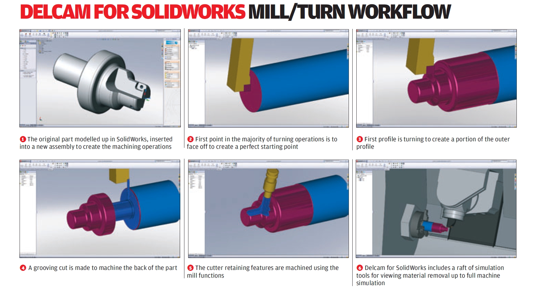
For those working on more complex tasks, such as 5-axis, mill/turns and specialised cutters, the system also includes full machine simulation, which uses an intelligent solid model of the machine tool to simulate its movement and find areas of clash and over reach.
Conclusion
DFS is a serious departure for the Delcam team. It’s the first time that it has taken its expertise and built it into another platform.
For a second release and certainly a first major release, as the 2010 version was more of a preview, it’s looking very slick. The majority of the tools needed by most machinists are there including production machining, mill/turns, surface machining and 5 axis.
There are a few things missing, in terms of support for multiple turrets in the Mill/Turn environment and there’s no wire EDM support, but I’m told these are planned for later on in 2011.
It’s good to see Delcam branch out from its roots and start to bring its knowledge and mastery of the world of machining to a much wider audience.
If you’re looking for a CAM system that’s built into SolidWorks, then I can’t recommend it more. Yes, there are other players out there that have been integrated into the system for some time, but this one is worth taking seriously.
Finally, as someone who is a great believer in integration, that if done properly can be very powerful then I recommend that you consider this.
As DFS can build machine tool-paths from native SolidWorks features and looks pretty robust at accommodating design change, mix in a bit of DriveWorks, the SolidWorks-based design automation tool, and things could get very interesting indeed.
| Product | Delcam for Solidworks |
|---|---|
| Company name | Delcam |
| Price | from £4,000 |