
The first generation of stress analysis was first introduced into Inventor around six or seven years ago. Based on technology from Ansys it allowed users to perform basic stress and modal analysis, but it had one major drawback – it only worked with single parts. While it gave a quick way for users unfamiliar with Finite Element Analysis (FEA) to get a foot in the door, the facts are that most engineering processes involve multiple components and the system wasn’t up to the job. As a result, those looking for analysis and simulation turned to the wealth of third-party Inventor-integrated simulation tools. This all changes with this release.
For Inventor Simulation 2010 Autodesk has incorporated technology from its recent acquisition of Plassotech to finally bring native assembly-based simulation capabilities to Inventor. Alongside the assembly analysis tools, the software includes parametric analysis functionality that automates the simulation of design configurations and variants, allowing the user to determine the optimum product design without the need to perform a time consuming series of repetitive analyses.

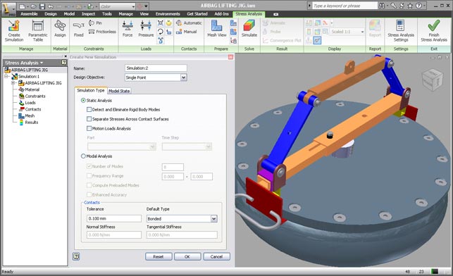
The new Ribbon-style user Interface of Autodesk Inventor Simulation 2010
So let’s dive in, work through the process and see what’s new and improved. The best place to start is the user interface. As with all things Inventor 2010, the interface is ribbon-based and works in a logical manner, presenting commands and options in a logical order, making it pretty straightforward to learn.
Idealisation & simplification
The first step is to decide whether you want to conduct a stress or modal analysis (natural frequencies). Inventor Simulation 2010 also offers the ability to analyse different level of detail representations of the assembly removing the need to create multiple copies of the assembly for stress analysis purposes.
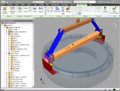
Exclusion of non structural components for simulation
Like the in-built analysis within previous releases, motion loads transferred from dynamic simulation can be used as well. The contact tolerance settings can also be altered to allow for the automatic contact generation between components that have clearances or gaps. Non-structural components of the assembly can be disregarded for the purposes of simulation by right clicking the component and simply selecting ‘exclude from simulation’ (see Figure 2). This will significantly simplify the analysis by reducing the number of automatic contacts produced and will speed up runtimes.
Setting up your study
Once the assembly model has been simplified to the desired level, the next stage is to apply load and constraints. Perhaps the most notable change here is the contacts and mesh control. There are various types of contacts available including bonding, separation, separation/no sliding, sliding/no separation, shrink fit (interference fits) and springs. The contacts between the components will be automatically created and can then be manually modified to any of the other available contacts. For example with the lifting mechanism in Figure 3 it’s very easy to alter bonded automatic contact between the bolt and hole to sliding-no separation contact-which simulates reality more accurately. While we’re talking loads and constraints, Inventor Simulation now offers an additional remote load type in addition to pressure, force, bearing, gravity, moment and body loads.
Moving on to mesh control, there are two types of mesh controls; global and local. Global meshing allows the user to control the overall size of the mesh, in addition to controlling the number of elements on a curve – for example, around holes. Local mesh control can be used to size the mesh on any component face or edge and is particularly useful for detailed and large components.
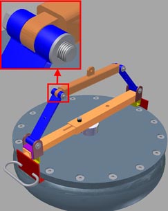
Lifting mechanism with bolt-type connections
Results convergence
Stress can become infinite if the area is very small, for example a point or edge (Stress = Force/Area). This is why it is advisable to avoid applying constraints and forces on points or edges as it will result in very high stresses – also referred to as stress singularities. It is normal practice to re-analyse the same model with different mesh sizes to see if the maximum stress changes, and if results are similar the user can assume results have converged – also referred to as manual convergence.
In previous versions of Inventor there was the ability to perform an automatic convergence of results where the software refined the mesh in the area of high stress. However, in cases where models were either constrained or loaded on points or edges the results did not converge using this automatic convergence process. This made the feature impractical for most analyses.
This deficiency can now be overcome in Inventor Simulation 2010 by selecting these problem points and edges and exclude them from the convergence results process. The results that can be used for this convergence process include von Mises, principal stresses and displacements (see Figure 4).
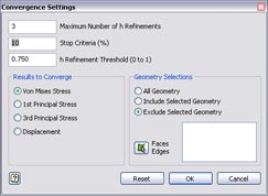
Convergence Settings dialogue box
The convergence can also be controlled by setting the number of iterations and the percentage stop criteria. This is 10% by default and was the criteria used in the previous versions –but could not be modified. One other unique feature of the convergence process is the ability to include part or all of the mesh elements of a model. A value of 0 will include all the mesh elements in the model as candidates for refinement –and can be useful when a model contains multiple peak stresses. A default value of 0.75 will refine the 25% of the mesh elements around the peak stresses.
Solve and results analysis
Inventor Simulation 2010 now offers a comprehensive list of results plots in addition to the von Mises, principal stresses and displacement, including planar stresses which enable plotting of tensile and compressive stresses in components (see Figure 5). In addition to displaying the maximum and minimum values, the user can now use the probe feature to pinpoint the key areas of interest in the model. This is especially useful when the model has maximum results distorted due to stress singularities present. Other useful additions include the convergence plot which illustrates that convergence has been reached and the uniform scale feature, which when activated allows users to see the results plot of an isolated component within the context of an assembly, without altering the maximum and minimum values of the colour bar.
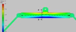
Tensile and compressive stress plot
Optimisation
Of all the new functionality in Inventor 2010 optimisation is the most impressive and allows users to see the affect that different design parameters have on defined goals and constraints including stress and deflection limits. Users can access design parameters by right clicking any component in the stress analysis browser and selecting Show Parameters (this is only available if Parametric Dimension is selected as Design Objective). The user can then select the parameters to be investigated.
Different design parameters, based on the original can be generated from within the parameter table within the stress analysis environment. Once these have all been done the user can define design goals and constraints from a predefined results list. This includes stress limit, maximum allowable deflection, factor of safety and minimise mass.
Once all the design parameters, goals and constraints have been defined the user can then begin to run the optimisation study. By default, the simulation will be set to run using the Smart Configuration setting that cleverly analyses a sample of the design parameters. The solution is reached much more quickly than when using the Exhaustive option that calculates every conceivable design parameter.
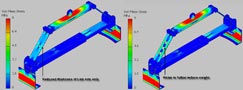
Alternative designs resulted from an optimisation study
Beware if you have a lot of design parameters, as the simulation can take a very long time. To get round this the user has the option of running the simulation by preselecting the design parameters for each feature (done using the parameter sliders) and then selecting Simulate This Configuration, which can be considerably quicker than running all design parameter configurations (see Figure 6).
Conclusion
This release of Inventor Simulation is a vast improvement over its predecessor, if for nothing else, by providing the ability to perform realistic simulations based on assemblies, rather than just single parts.
The Parameter studies functionality is also very important. This helps users explore the impact of design parameter changes, against defined design goals and constraints, without the need to investigate and analyse an excessive number of options – with the ability to promote the optimum design parameters to your CAD Models. All in all it greatly helps to analyse and modify designs efficiently enabling users to turn around designs faster by working seamlessly with the CAD models, helping to reduce costs, reduce failures and thus warranty costs. However, there’s still room for improvement.
Within future releases of Inventor Simulation I’d like to see additional functionality including buckling, thermal and CFD analysis, plus more post-processing functionality including dynamic probe display, clip planes and the ability to compare results from different studies side by side in the graphics windows.
| Product | AutodeskProduct: Inventor Simulation 2010 |
|---|---|
| Company name | Autodesk |
| Price | on application |


