Founded in 2001, Silicon Valley-based Luxology is the maker of modo.
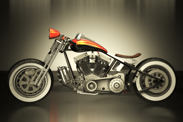
modo 601 not only produces stunning visualisation assets, but with the new CAD loaders and PowerNURBS, brings the power of Sub Division Modelling to the product design world
modo is an integrated modelling, painting, animating and rendering software package that is used in the entertainment, gaming, advertising and visualisation industries. Luxology has long been a leader in the domain between computer graphics and design – the ‘CAD to Ad’ connection.
Luxology’s vision for the merging of these two worlds was first manifested a few years back in modo 401 with the ability to import Solidworks models. This capability was born of its collaboration with Solidworks to build the popular stand alone rendering software – PhotoView 360 (PV360). Luxology licenses its render engine to Solidworks for use in the integrated version of PV360.
Later, Luxology developed a user interface (UI) and tool set – Solidworks Kit aimed at Solidworks users who work with modo.
Recently, Luxology has developed a wider format CAD connection by offering the ability to import common file formats into modo, such as Parasolid, IGES, STEP. The geometry translation is very efficient and produces a favourable mesh topology.
Luxology’s solution is focused on a visualisation based workflow from the CAD asset to modo. This workflow is excellent for creating stunning visualisations and animations with highly accurate data.
Once again Luxology has influenced the domain between art and engineering. Collaborating with IntegrityWare, it provides a refi ned workflow solution for data from modo back into a CAD package. The PowerNurbs plug-in is the engine to convert modo files into a CAD friendly format.
Sub division surfaces
In today’s 3D modelling world, there are a few types of modelling methods. Two of the more prominent are NURBS (Non-Uniform Rational B-Spline) surface and Sub-Division Surface (SDS) modelling. NURBS modelling is used by CAD packages like Solidworks.
Luxology’s modo utilises polygonal and SDS modelling. SDS and NURBS modelling are designed for different purposes and are totally different modelling methods. Each is very strong in given areas.
SDS modelling is excellent for complex organic surfaces but requires a high degree of skill to perform ‘hard surface’ operations such as holes and hard edges. NURBS modelling is excellent at hard surface operations such as extrusions, holes, swept cuts, fillets, etc. However, it requires a high degree of skill and knowledge to perform ‘organic surface’ operations.
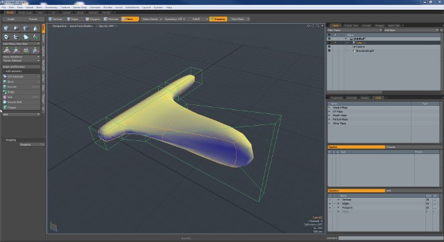
Because SDS is an approximation between points, edges and polygons, it is by design a ‘smoothing’ algorithm. The control ‘cage’ can be thought of as a structure that ‘expands’ the geometry and the mesh can be thought of as a stretched balloon (Figure 2). This modelling is not meant to be highly accurate but merely representative.
One of the bigger challenges with SDS is what is termed ‘hard-surface’ modelling. ‘Hard surface’ items are things like sharp corners, holes, mechanical parts, etc.
In SDS modelling, the lexicon is populated with terms like topology, quad-polygon and N-gon. Topology, which is the ‘flow’ of polygons around a surface, is paramount for producing efficient models. SDSmodellers are often praised for the efficiency at which topology on a hard-surface is executed.
CAD modellers are accustomed to being able to easily produce these types of ‘hard’ features. Their paradigm is working from a solid block of wood or plastic and extruding and removing material to produce parts.
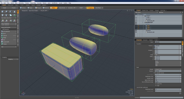
Cutting a hole in the side of a part is a very routine and simple function. The CAD modeller is not concerned with how this will affect other areas of the geometry. An SDS modeller has to always be aware of adding geometry and how it will impact other parts of the model (refer to Figure 3 to see how edge rows change the shape of the model).
As the edges are increased, the model shape is altered. These edge rows can cause undesirable shape changes in other portions of the model. The SDS modelling toolset is well suited to producing complex organic shapes, particularly when compared to surfacing with a traditional CAD package.
The tools are more intuitive with SDS, while organic shapes in a traditional CAD package can be difficult to manage. Given the choice to model hard surface parts, NURBS is the best option. Conversely, if one was to model organic surface items, the SDS paradigm is the best selection.
In product design, for example, a model often requires organic and hard surface shapes. The modeller would have to make compromises in efficiency or become highly specialised in the area of the modelling paradigm’s weakness.
The opportunity of being able to combine the two modelling methods is to truly combine the best of each to produce a streamlined workflow.
New tools to help
With the advent of the PowerNurbs plug-in for modo, the design conceptualisation workflow has been vastly improved.
The PowerNurbs plug-in is all about streamlining the path between Sub-Division Surface (SDS) modelling and NURBS modelling. The promise is utilising the strengths of each to significantly enhance the overall workflow.

One immediate application is for seamless integration for conceptual design to manufacturable part.
SDS can be used to block out and develop the overall shape of the part while utilising NURBS to develop the accuracy required for manufacturing.
Using the inherent organic surfacing capability and tools of an SDS modeller, gives the user an opportunity to handle the model more directly.
It can be thought of as a digital clay modelling process where the asset can be directly imported by the CAD software.
From there, the user can further refine and enhance the design for manufacturing. Users that will benefit from this workflow are those who are interested in design conceptualisation and turning it into a manufacturable part.
Rendering feature updates
modo 601 is a massive upgrade and there are far too many features to mention here. I’ve highlighted those that may be of most immediate interest to those looking at modo from the perspective of both product design and visualisation.
Rounded Edge Shader: The rounded edge shader is a massive time saver and is great at helping the artist achieve realism. When the user renders CAD objects, often the corners are perfectly sharp.
This contributes to the overall ‘computer generated’ look that may not be desirable.
By putting rounded edges on the corners, a more realistic result can be produced. But this can take a lot of time. Now with the rounded edge shader, by material, the user can easily specify the rounded edge radius and then modo will do the rest at render time (Figure 4).
Cell Edges: This feature is excellent for producing compelling images of the CAD data. A number of looks can be achieved but in this case, I used it to produce a technical drawing feel for the motorcycle (Figure 5).
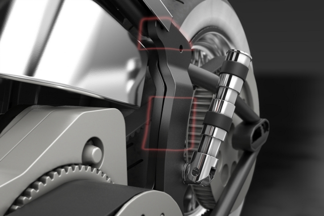
Render booleans and Camera Clipping: This feature is a major win for visualisation professionals. As discussed above, SDS and polygonal models are ‘hollow’ and don’t do well being ‘cut’.

This uses a mesh and other 3D shapes to cut-away portions of the model.
At render time, the areas specified by the user (via a clipping plane, primitive object or mesh) will be cut away and the resulting mesh holes will be filled in completely.
This is an enormous time saver because it allows the user to quickly and easily specify the area to be cut away (Figure 6).
Render Passes: These allow the user to maintain a number of iterations of a scene simultaneously. Practically anything in the scene can be changed and saved as a render pass.
Users can control parameters and how they are varied. The great thing is that each iteration can be rendered at one time.
Conclusion
While I’ve covered the highlights of this modo release, there are many other areas that are worth exploration by design focussed users, such as both soft and rigid body dynamics, animation and new deformers.
Yes, other vendors are introducing complex shape modelling into the CAD app but the power of modo for visualisation and modelling is highly attractive.
What should be clear is that the domain between art and engineering has been bridged now with a two way street. One way is the path of visualisation.
The other way connects the organic modelling of DS with the manufacturing tools of CAD. Luxology has positioned itself firmly in the middle between the CAD and Ad worlds by offering a round-trip solution between SDS and NURBS modelling.
While this workflow is still young, the future looks bright for product design that requires organic shapes. The next step is the opportunity to be able to interact with the imported SDS model in your CAD program.

Biography: Paul McCrorey, McCrorey Digital
Paul McCrorey is a CG artist and Engineer who runs a 3DVisualisation company, McCrorey Digital, producing stunning visuals and animations.
An ambidextrous thinker, Paul is a domain expert in the area between CAD and Ad 3D market sectors being able to speak both languages fluently. He is passionate about visual communications and helping people ‘get it’. He’s also the Founder and President of the SolidWorks Louisville User Group.
| Product | modo 601 |
|---|---|
| Company name | Luxology |
| Price | From $1,195.00 |