Autodesk’s generative design technology has been discussed for some five years now, but it has finally made it to Fusion 360. We walk you through what to expect if you decide to dive in and give it a whirl
Autodesk has been talking about generative design for quite a while now, stretching back to 2014, when executives began hinting at a future technology research project called ‘Dreamcatcher’.
Generative design technology is built directly into Fusion 360 and payment for computation is made in cloud credits
While the term ‘generative design’ originated in the architectural design technology field as a way to describe the generation of multiple part designs from a single set of scripts (see Rhino’s Grasshopper applications), it has since been co-opted by several vendors in the mechanical engineering space as a way to rebrand decades-old topology optimisation technology.
What’s interesting here is that Autodesk’s definition has perhaps been most loyal to the true origins of the term, as we shall learn.
Either way, in the time between 2014 and now, almost every Autodesk keynote presentation and corporate update has mentioned generative design – to the point where you might have been forgiven for expecting the Second Coming, rather than a nifty-looking bit of design and engineering software technology.
Thankfully, the hype train came to the end of the line towards the end of last year, when the Fusion 360 team finally updated the system to include the first variant of this technology as a real-world, commercially available product.
Study definition
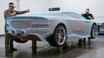
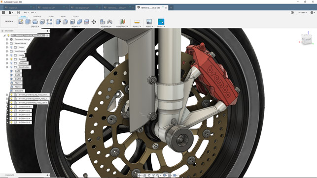
The place to begin with generative design is to define the geometry that will provide the basis for your exploration of the technology.
As you might imagine, there’s a whole host of tools available in Fusion 360 that will allow you not only to create geometry from scratch, but also to repurpose existing geometry if you’re looking at a redesign or re-engineering project. But what is it that you need to model up?
It’s at this early stage where we see one of the main points of difference between Autodesk’s approach to these tools and that used in other topology optimisation based systems to provide similar results.
Topology optimisation does exactly as indicated in the name: it optimises a given set of topology against a defined set of loading conditions. Essentially, you define an explicit optimisation domain and the system works from there to remove material accordingly.
Generative design, by contrast, allows you to work without an explicit domain – and this is fundamental. During the set-up stage, you define any geometry that you require (such as mounting brackets or interface geometry, for example), and then define obstacle areas, where you do not want any material present at the end of the process (for clearance of other components, for example, or movement of an assembly). In theory, this is all you need to do for the system to handle the creation of the domain for optimisation – but that’s a rather gross oversimplification.
For those used to working with more traditional optimisation tools, this domain-less approach takes a little time to sink in, but it can be powerful as a tool for experimentation, since you’re not immediately restricting the potential form of your part.
At the same time, it can be a challenge to consider your project in this new way and you may need to iterate your problem definition in order to fine-tune it. If you do have an explicit volume inside which you need to work, there is the option to give the system a starting volume.
This automatically restricts geometry to this shape – but it’s a shame to nail things down so firmly during early-stage experimentation.
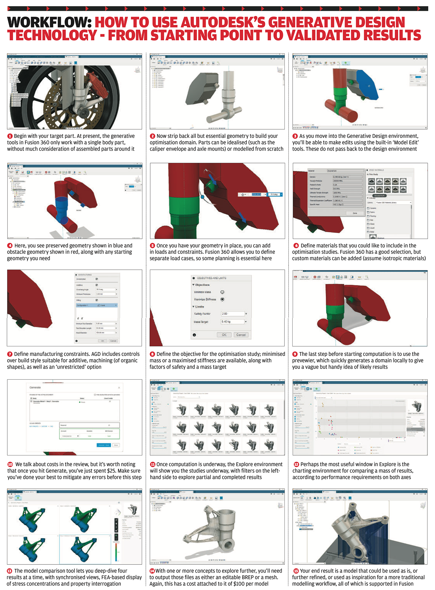
It’s also worth noting that the Generative Design Workspace contains a sub-set of tools to help you abstract a model from an existing set of parts. This is useful for making smaller edits as you go through this period of iteration.
There are also tools that help to save time; a good example is the fastener obstacle tool. This allows you to veryquickly model up a shaft for a fastener, and add in a bolt-head and an additional cylinder on top, for ensuring bolts/screws can be accessed with the appropriate tool.
Loads and constraints
The next step is to start to define your loads and constraints. Constraints are pretty straightforward: you can define fixed, pinned and frictionless constraints, locked to the axes you need. You can then start to define the loads on your part.
Again, you have a set of common loads, including forces, pressures and bearing loads. These are applied in distinct sets of load cases.
There are a couple of things to note here. The first is that each load case definition is weighted equally during computation.
The second is that loads and constraints can only be applied to the ‘preserved geometry’ that you have defined; this is absolutely key and might be the cause of some iteration during set-up. In other words, good planning is required upfront before a project begins.
Materials, manufacturing and objectives
Once your load cases are in place, the next step is to start to define the material and manufacturing aspects of the project. This is split into two steps. The first step is to select your materials.
Fusion 360 comes pre-set with a wide range of material definitions (with the option, of course, to add to this range.) This is done from the familiar materials dialogue: you simply drag and drop your requirements into the window at the top of the dialogue. It’s worth noting here that the maximum allowable number of materials per study is 10, at least for the time being.
Then you move onto the definition of manufacturing constraints. These are the constraints that control how the system should approach building geometry to solve your loading conditions. Generative design in Fusion 360 has some interesting options and these are expanding with each update. The most open option is to have the system work in an unrestricted manner. This means that it will build to optimise, without thinking about manufacturing method or processing.
Then, you move into additive options. This allows you to define a number of controls over geometry – specifically, overhang angle and minimum thickness of material allowable.
You then get into the milling methods. You can not only limit the geometry to an axial direction (so that all features can be machined from the defined directions), but also have it respect your requirements in terms of number of axes (3- and 5-axis is available), minimum tool diameter, tool shoulder length and head diameter.
With these, you can just about define the parameters of your machine tool capability.
The last set of parameters you must define is the overall objective for the optimisation process. At this point in time, there are two options: reduction of mass or maximisation of stiffness.
Typically, in an optimisation process, you have a mass reduction percentage, but with the Fusion 360 generative design approach, you don’t have a starting volume or mass, so you have a target mass that the system tries to achieve.
There is also a factor of safety, so you can dial in how close you want to run things to the bone. (It’s worth noting that any optimisation process is working on the basis of idealised inputs and outputs, so factor of safety is really important here.)
The last stage is to use the newly added Previewer tool. This will take a quick scan of your job and generate a pretty rough optimisation domain for your studies as a greyed-out lump of geometry. This gives you a very quick sanity check, indicating the direction your studies might take and possibly flagging up any glaring errors.
Computation and costs
Now that you have your geometry set up, with loads, constraints and optimisation parameters in place, the final step is to compute the study. It’s here you start to use your cloud credits, either supplied with your subscription to Fusion 360, or drawn from a company pool. At present, there is a fixed-rate cost of conducting a generative solve of 25 cloud credits, which at current pricing is $25.
At this point, it’s worth considering what the generative design technology in Fusion 360 is actually doing. It is taking your load case and geometry and creating a matrix of studies that sees every material option run through with every manufacturing option you’ve selected. If you max the system out by selecting the maximum allowable materials and clicking on every production option, you’re likely looking at a 10×10 matrix; in other words, 100 optimisation runs at $0.25 each.
You also need to consider how quickly you need your answers back. Each computation is iterative in nature (typically resolving in around 25 iterations). If you add in more materials than are needed or more manufacturing variations, you increase the amount of computation required. Conversely, you’re paying for it, so if you have time, max out your options and see what comes back.
Exploring results
Either way, at some point, you need to make the call and hit that ‘Generate’ button. The system packages the work up and sends it for computation – and this is where things get really interesting.
Simulation is often a non-interactive process: define your results, send to compute, and come back to your results (if you’re lucky).
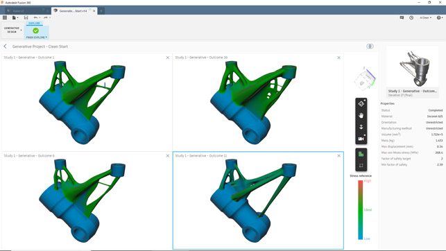
With generative design in Fusion 360, by contrast, as you start computation, you can enter the Explore environment.
This gives the user a window into the experimentation that the generative design solver is performing.
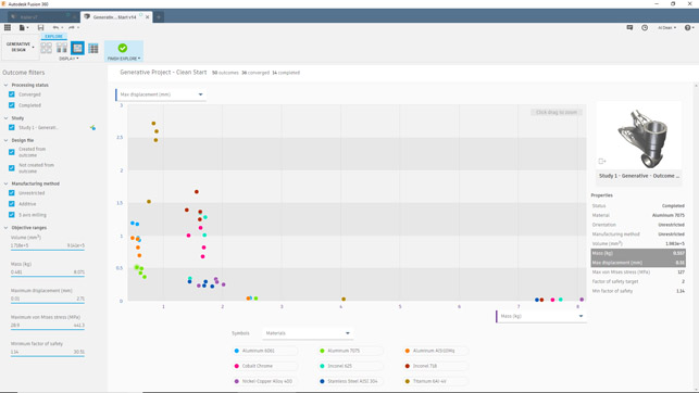
On opening it up, you’ll be presented with a grid-like window that shows each study underway, with a bunch of filters to the left-hand side. Each of these shows you the current state of a study in terms of geometry, and you can quickly arrange them by material, maximum stress, volume, completion stage and more.
There are another couple of ways to view this data: as a grid; as a grid with expanded properties; or most interestingly (to my mind), as a scatter plot that plots your current studies against two properties of the study/results.
By default, this shows you factor of safety versus mass, where each study is plotted against those axes, but these can be switched to whatever properties you’d like on each of the axes.
Combined with the filters and grouping/colouring options, you can very quickly gain an understanding of how your experiments are progressing or have completed and where they lie on the performance front.
When using any of these results inspection methods, it’s possible to both dive into the results individually or select up to four for close comparison.
The comparison environment allows you to have up to four concepts on screen at once, with synchronised views and inspect tools, ranging from standard pan/zoom/rotate, to display of stresses on the parts, design space ghosting, and more.
It’s worth talking at this stage about the different end results of each study. Some concepts will fail, due to a range of issues. Some will complete, but not converge. Others will both complete and converge.
Convergence is a term that’s widely used in the simulation world and can be applied to a number of different factors, but within the context of generative design in Fusion 360, it means that strain energy history change, factor of safety change, and volume change have normalised over the last 10 iterations, so the system is confident that the requirements have been met and the concepts are robust.
So, what’s next? You have a range of tools to do some basic inspection of results, but chances are that you’ll want to take these further. It’s here that having these tools built into a full-featured modelling and manufacturing system like Fusion 360 comes into its own.
Progressing projects
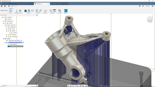
At this point in our workflow, we now have a shortlist of concepts from the generative design process that have both completed and converged. These are available to inspect within the Explore environment, but to progress things further, you need to export each concept that you’re interested in from the generative design environment to the regular design environment, either as a b-rep model or as a mesh.
The mesh is just as you would expect – a high-resolution triangulated mesh of the result set. The b-rep model is a little different. The Fusion 360 team has worked out a way to combine both the preserve geometry from your study and convert the mesh-based results from the generative design process into a complex, but editable, t-splines model (the Fusion 360 variant of sub-d modelling tools).
This can be created either with or without an intact construction history and can then be taken through further workflows and validation, and eventually, perhaps, into production.
This is where, in Fusion 360, you incur more cost, because to export concepts is going to cost you 100 cloud credits.
That, on the face of it, might sound a bit off. The reality is that you’re not really paying a huge amount for the software in the first place. (Remember, including all of these tools and much more, it’s £54 per month.)
There’s also the fact that this type of software is using resources off-loaded from your workstation (and on Autodesk’s dime).
Compared to the ‘all-you-can-eat’ approach to engineering software, this is where things are heading. You might not like it (and I personally have a few issues with it), but it’s a good indication of the adjustments many users will need to make.
If there are things to look out for at this stage, the big one is the t-splines model, if you’re looking to use these parts directly. While you have a robust set of geometry that you can use Fusion 360’s native editing tools to manipulate, if you’re looking to run it through the Fusion 360 simulation environment, you might encounter a few issues when it comes to meshing such data.
Yes, the generative design technology does carry out a cursory simulation using your load cases, but this won’t be enough to validate whether these hyper-optimised forms can withstand real-world loading conditions.
They can then either be placed into the context of assemblies; or used as the basis for machining operations or preparation of data for casting; or, in coming releases, prepared for additive manufacturing (the latter is in technology preview at the moment).
Indeed, a mix of all three is entirely possible, too.
Consider a part that is additively manufactured to start with (as per our example). You’ll also be able to use the Fusion 360 modelling and CAM tools to develop jigs/fixtures to carry out those inevitable post-build machining cycles, such as facing off mating faces, thread or other operations.
The final stage is, of course, to manufacture one of these parts. Fusion 360 supports a range of manufacturing approaches, from additive (currently in preview) to more traditional methods such as machining
In conclusion
After some five years of hints and promises, Autodesk’s generative design technology is finally here. And from what we’ve seen, after just under six months on the market, it shows huge promise.
There is a natural instinct to compare this set of tools to the more common topology optimisation tools available in other systems (including Fusion 360) – and, at present, the results appear similar in nature. But to do so would be a fundamental mistake.
As we discussed at the outset, topology optimisation refines a singular form to an optimised state, typically using a singular material. Generative design in Fusion 360 is, by contrast, a platform for experimentation on a much grander scale.
The fact is that you are generating, without a great deal more effort, potentially hundreds of ideas and avenues for exploration.
You are able to explore not only material variations, but different geometry controls (and hence, manufacturing methods), meaning you can truly explore your design space. Yes, the problem definition capabilities need a little more maturity. Yes, there needs to better ways to document the process and to shortlist potential solutions, but what we have here is already a great start.
The issue of cost, of course, will need to be considered by all prospective customers. On one hand, being charged to obtain results from a system for which you’ve already paid a subscription may seem counterintuitive and unhelpful when it comes to project budget forecasts.
On the other hand, the ability to run optimisation studies across a matrix of inputs and parameters, as you can here, would take days, if not weeks, of work to set up manually. And then you would still have an enormous amount of processing to do in order to compute it and sift results.
There is more to come in Fusion 360. Some of the updates teased at Autodesk University last year included one variant of the geometry controls that only builds prismatic shapes, while another looks for beam-based solutions, allowing users to scheme out a framework (perhaps based on CNC cut and welded tubing) using the same approach.
There’s also rich potential to expand this system to include multiphysics simulation and to expand the remit beyond simple part geometry and into assemblies (which might be particularly useful for more accurate loading cases in the first instance.)
All in all, what Autodesk has delivered on here, in its first pass, is pretty damned impressive. For those looking to explore new materials options, new manufacturing options or to open up their design engineering work to new ideas and experimentation, it’s a launchpad for new journeys.
Design and engineering thrive on experimentation, of course. It’s what we, as a community of professionals, have always done.
Now, it seems, we’re seeing a new class of tools that can support that process and give it a huge boost, thanks to the unprecedented levels of computational power that we have at our disposal today. Strap yourselves in, it’s going to be a fun ride.