Fusion 360 has been growing since we last looked at it. Sheet metal, PCB interaction tools and browser-based modelling have only recently been added. We dive in to find where things stand toward the end of 2017
Let’s recap on where we’re at with Fusion 360. From its roots as Autodesk’s experiment in direct modelling it has grown to a cloud enabled product development system that covers the gamut of solid, surface, subD (well, t-splines) modelling, drawing creation and all the collaborative and project management tools that the cloud implies. The system has been available commercially since 2015.
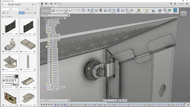
After a year or more of waiting, Fusion 360 users are finally getting the sheet metal tools they’ve been waiting for — and they don’t disappoint
Alongside the CAD tools, the system has grown in many other ways — we’ve seen machining and CNC programming (from HSM), simulation based on the Nastran solver, advanced visualisation, mesh handling and much more. With each, nearly monthly update, the system has grown in both capability and maturity.
So shall we have a look at where the system is now in September 2017? Let’s begin with some of the key updates to the core 3D design tools.
Fusion 360 – core modelling updates
The first area relates to blends. This is something notoriously difficult to create in most circumstances, but when thrown into the requirements of the tooling design industry, it can become a highly complex task.
For this latest release, there have been a couple of updates that are worth talking about, particularly for those that are developing both more complex assemblies based on sketches as well as complex surfaces.
On the sketching front, one of the most useful additions since we last looked at Fusion 360 is the ability to copy and paste a sketch between parts. Although this will save a lot of time, it’s just a shame, considering Fusion 360’s cloud and project management tools, that you can’t store them separately to make reuse much easier.
Elsewhere in sketching, you can finally add in a dimension between two arcs based on tangency. It might sound like a small update, but if you need this type of tool, not having it means endless amounts of tapping in dimensional equations.
Moving onto more complex feature creation, we’re going to look at the loft options. While loft has been in the system for a while along with some basic controls over tangency and curvature, the latest update allows you to not only defi ne a curvature continuity (G2) control to loft profiles, but rails as well, so your geometry matches nicely.
Much of the big noise around Fusion 360 has focussed on T-Splines and the Sculpt environment when it comes to complex shape design. However, the reality is that this isn’t a do-it-all tool and, in many cases, you’ll need to be able to strip back to basics, construct geometry from scratch, use the “Patch” operations (which contain the traditional surfacing tools) and build up those complex transitions using more traditional tools.
This update adds to that arsenal of tools.
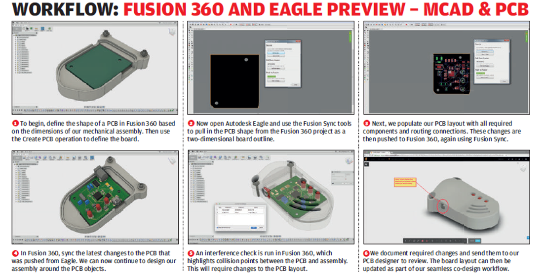
The latest release of Fusion 360 introduces a preview of integration between Fusion 360 and Eagle
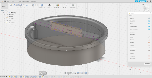
Fusion 360 – sheet metal – art to part
This is perhaps the biggest news into Fusion 360 for 2017 so far. While it has been previewed to some users over the last year or so, this is the first time that sheet metal part design will be generally available.
So how does it look for a first release? The answer is that while they’re not a complete set of the tools that an Inventor or SolidWorks user would expect (which have been developed over a decade or more), right now they are usable and their simplicity perhaps belies some of the functionality contained in them.
Whereas in a tool like Inventor, you’ll find all manner of operations for sheet metal design, in Fusion 360 you have a very simple set of tools — Flange, Extrude and Hole/Thread. While that might not sound massive, you can get a lot done with them. The flange, as you’d expect, is key to this and the development team has done a good job of hiding more complex decisions and operations from the user and driving much of it from your selections.
Consider starting with a closed sketch of geometry. That sketch could create a base flange from which you build additional flanges. If you select the contour (the area inside that sketch), this is what you’ll get.
If you select the edges instead, you’ll be able to pull up those edges as individual fl anges, with the system adding in the bend radii where needed.
As you’d expect the system contains a sheet metal rules database, which can be used as is or can be adapted to your material and fabrication needs. While that’s pretty standard, it’s interesting that when you create each feature. You now have the ability to momentarily override those rules from within the dialog, allowing you to account for special cases where you need a tighter radius bend or a slightly different corner relief form.
There are also greater controls within that fl ange. Each edge you select can be built differently — whether you want to build your flange along the complete length, you can add in symmetry offsets or even drag each end separately — all of which remain editable.
Alongside the core flange tool, you have tools for adding extruded cuts from the sheet forms, adding in holes and threads and such. You also have the full set of Fusion 360’s modelling tools to both add in features as well as edit forms, patterning and mirroring.
Though some care has to be taken to ensure any features added conform to sheet metal design tools if you’re looking to maintain your flattened form correctly.
Then, of course, it comes to flattening out those forms. The system has two unfolding operations. The first, “Unfold Part”, allows you to quickly switch between the folded and unfolded form, both to add features that span gaps as well to experiment with unfolding options.
The more formal “Create Flat Pattern” flattens out your part and stores this as a formal part of the feature tree. From there it can be referenced for drawings and such.
There are a few points to note as you dive into these tools. The most important is that if you’re looking to build more than one sheet metal part in your assembly, you need to plan it out first and create a fresh component for each.
While Fusion 360’s multi-body modelling approach is powerful, you can get carried away with creating multiple sheet metal bodies in the root of your model, but you’ll quickly find that you get stuck as each ‘model’ can only have one flat pattern associated with it. You can’t create components from bodies as you can with regular geometry. You need to partition it off into a component before starting, then you’re golden.
When it comes to documenting your parts, there’s a nice workflow that allows you to add drawings to sheet sets (that’s been added to Fusion 360 recently), you just need to create and name the sheets for each part.
You then choose the “Create Drawing” option from the right click menu, define the parts, the state (folded or unfolded) and the target sheet. Then you work through the process of laying out the views. As you’d expect, there are tools to assist with sheet metal documentation, including automatic generation of bend tables and bend documentation.
Of course, for most 3D design systems, this is where the sheet metal stops.
The drawings are made, a DXF file is generated and sent off to the fabricators or suppliers. Fusion 360 is a little different — it has had CAM tools for CNC code generation for a couple of years now. While most of these tools have focussed on the programming of mills (and more laterly, lathes), it also has a set of tools for programming laser cutters and waterjets.
Fusion 360 – PCB design
In 2016, Autodesk acquired CADsoft, developer of the PCB design system Eagle. While it’s not as functionally rich or enterprise focussed as tools from the likes of Mentor, it has found a home in many businesses.
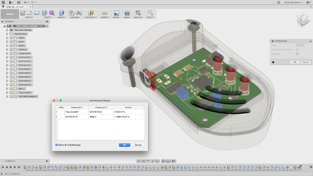
At the same time, the company has been increasing the connectivity between this system and the more mechanical design aspects, which for those that are engaged in such work, is all about iterating between mechanical design of the board and components and how they interact (or, should that be, interfere) with the other components in a product.
To assist with this, Autodesk has just introduced a preview of functionality that links the CAD layout and schematic design tools in Eagle with Fusion 360’s mechanical design. Whether it’s loading a PCB layout from Eagle and populating a Fusion 360 assembly or using Fusion’s tools to design the basic layout or tweak component positions and pass that data back to the PCB design environment.
We cover the basics of the process in our workflow below and it works nicely, even at this formative stage.
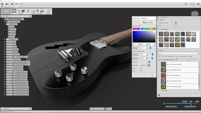
Fusion 360’s rendering environment has seen a lot of work on materials and scene setup as well as achieving parity between the cloud and local engines
Fusion 360 – rendering & visualisation
Fusion 360 has included rendering tools for some time, for both static images and animations based on the built-in tools.
Alongside this, the system has included both a local renderer that uses your local computation on your workstation, along with a cloud-based renderer when you want to off load those larger tasks from your machine or you need to keep it free.
Until recently, the two rendering solutions used different engines to produce the images and, as a result, there was a mismatch in some materials (they weren’t fully cross compatible between the two modes). The good news is that the local renderer (based on decades old Opticore technology) has been replaced with the same engine as found in the cloud renderer. This means that the two are fully compatible and you’ll be able to output imagery from both without grappling with different material definitions.
To enlarge image click here
Fusion 360 – CAM & CNC
The CNC tools in Fusion 360 have been growing with each release. The tool set is pretty well developed, from a component set of 2.5 and 3 axis machining — with more recent releases starting to move into the world of 5 axis positional as well as turning. Those tools continue to grow, but there have also been some interesting changes to better support a more centralised way of working.
Part of this focusses on the use of the cloud-based nature of Fusion 360, with tooling libraries now being fully cloud enabled, which makes it much easier to have multiple users (or indeed, a single user with multiple use places).
The tool library has also seen some major rework, with the whole thing feeling more organised and much more efficient when you’re looking to both narrow down options from standard tooling to, most likely, creating your own from scratch.
Elsewhere, the team has also started to flesh out a library of standard fixturing and work-holding. While this focusses on predominantly US-based vendors, there’s a good spread of options to work from.
Also, we mentioned earlier, the tools for programming cutting machines, whether that’s waterjets, plasma or laser cutters, this has now moved from preview to released state and the tools are available to use in a production basis.
Alongside the more traditional forms of machining that are growing inside Fusion 360, the last few releases have seen the introduction of a different approach that centres on the machining of not solid or surface geometry, but meshes. While for the hardcore machinist, this will be akin to blasphemy, for those that are using CNC machine tools in the design office, perhaps for machining foam models or packaging mock-ups (even for more complex sculptural forms), it’ll be perfect.
Rather than having to work through and program different faces and features, operating on individual areas, you can use a mesh approach to generate more holistic operations that will focus on creating the final form in a set of very simple operations.
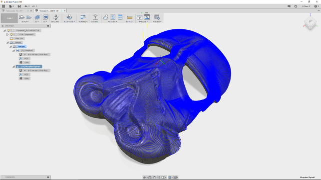
In recent releases, Fusion has also brought in the ability to machine over a mesh. This is super useful for those working with more complex forms and at the prototyping stage where surface finish is key, but operation efficiency isn’t quite as key
In conclusion
Looking at the breadth of the updates to Fusion 360 since we last looked at it (at the tail end of 2016), the advances made in the system are pretty breathtaking.
At that point, nine months ago, we’d seen the introduction of simulation, expansion of the simulation tools (some of which are still in preview mode) and hints at the browser based way of working.
Fast forward to today, we’ve seen the addition of sheet metal design, documentation and production, browser based design (which might prove useful when you’re in a jam) and much more.
All that in nine months — a set of updates that some vendors would take years to implement.
Yes, some areas are still in work, but there’s an interesting trend throughout all of these updates. Some are bringing new functionality to an already rich software solution, but others are starting to mature and what you’re seeing is Autodesk address the needs of that maturity – adding in the smaller, but equally as import tweaks to operations, commands and workflows that take the system from being useful to becoming truly productive.
But let’s not get too carried away.
After all, the idea of an integrated CAD/CAM/PLM system isn’t particularly new. Systems have been available that cover everything that Fusion 360 offers and have been available for decades. But, and this is a very important ‘but’, the cost differential is huge.
Consider that the standard Fusion 360 licence is $40 per month or $300 per user per year. The Fusion 360 Ultimate, which adds advanced simulation and machining onto that, costs $190 per month or $1,500 a year. No up-front costs, no add-on costs for data management implementation, post processor authoring or customisation. I’ll repeat that.
For 3D design, 2D drawings, photroealistic rendering, simulation, machining (including 5-axis positional) and now electronic-mechanical with Eagle (this is an additional cost), you’re looking at a shade over a grand and a bit a year.
To buy that same level of technology ten years ago, you’d have been looking at ten times that price as a minimum easily for just the maintenance and, in many cases, probably still would.
Fusion 360 is undoubtedly supporting a more dispersed approach to product development that’s more common than ever before and doing it with a set of efficient and flexible tools that allow you to work on projects from whatever point you jump into the process, whether that’s concept design, detailed engineering, documentation, simulation or into production and fabrication.
But perhaps most interestingly, it’s doing it in an environment that allows a team to use the same tools, not because they have to, but because they can all afford it. The last few releases have combined the addition of new tools and growth of capability with adding maturity and depth to the existing functionality.
Fusion 360 in the browser — looks very similar to the existing local install/stream, but runs without any heavy downloads in most modern browsers
Data management and access: Online, offline & browser
When launched, Fusion 360 was amongst the first cloud-based tools for design, a field which we’ve seen grow in recent years. Fusion 360’s take was to provide a local set of software that synchronises to a cloudbased file and project management system, built onto Autodesk A360 platform.
While this made collaboration and delivery of the software pretty simple, if the software went off line or you didn’t have internet available, you were pretty much stuck with creating new data or hoping that you’d got your required file open at the time so that you could continue with your work.
In the last few months there has been a couple of updates and additions to Fusion 360 that make this state of affairs both more flexible (in terms of software availability) and more robust (in terms of data availability). So we’ll explore these.
Cross project references
This year, Fusion got the ability to insert part or sub-assemblies from one model to another and the ability to maintain that link. So, should any updates be made to that model, they’ll be refl ected wherever they’re used.
If there was an issue, it was that this only worked in the context of a single project, so parts or sub-assemblies couldn’t be referenced between projects.
The good news is that in the most recent update, Autodesk has introduced a preview for inter project links, so you can insert data from any project into any other one. While it’s at preview stage (which means it could be replaced or removed), its a good indication that Autodesk is exploring the finer points of what it has on their hands and is looking to address some of these core issues.
Of course, this also opens up the possibility of reusing much more data, centralised standard or commonly used parts across a design team and generally making life much more efficient.
Selective caching of data
This was introduced in the last big update and for those that have unreliable internet or a period where they know it’s not going to be available, it’ll be a godsend.
Fusion 360 synchronising tools have, up to this point, been a bit hit and miss.
If you knew you would lose your connection, you pretty much had to make sure you opened your data before you went off line. Something that isn’t always the case.
From this point onwards however, Autodesk has introduced selective caching at a project level. If you know you’re going to be offline and need that project’s data, you hit the switch (found in the data panel, right click on the project and choose “Cache this project” from the menu).
Fusion will then ensure that you have a localised cache of that project when you need it.
When you get back on line, Fusion will also rationalise any changes you made. But, how the system handles any changes made by someone else sharing that project, isn’t quite clear yet.
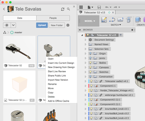
The new Insert into Current Design now allows you (assuming you’ve switched on the preview functionality) to cross link data between separate projects
Fusion in the browser
A year or so ago, Autodesk started demoing a browser-based version of Fusion. No software stream or install and no plugs ins — just a modern browser and a web connection.
It has just started to preview this to everyone and it’s found in the project files in Fusion Team (which is the web-based project and data management service). Find your project, locate your data and you can either create new parts or edit existing ones. The capabilities are pretty much limited to prismatic solid-based modelling (think: extrudes, revolves, lofts, fillets and sketching), but they’ll allow you to make general edits to your parts or quickly sketch out a new set of geometry.
If the command for creation isn’t implemented it does mean you won’t be able to edit those features, but if your part is simple, you’re good to go.
What happened to Branch and Merge?
Branch and Merge is an approach to project management that’s gained dominance in the software engineering world but has only recently started to gain some attention in the product design world.
The approach allows you to explore form, function and variation as a project develops. Fusion 360 got a preview of Branch and Merge capabilities in its project management tools over the last year. If you’d switched on the preview, you’d have been able to experiment with them, but Autodesk has chosen to remove the current iteration and reevaluate how it might be implemented.
To read our interview with Autodesk’s new CEO Andrew Anagnost click here
| Product | Fusion 360 |
|---|---|
| Company name | Autodesk |
| Price | See text |