In prototyping workshops, CNC is becoming more and more popular. It’s been a hot topic in recent issues of DEVELOP3D and, with the rise of low-cost CNCs, many designers and engineers are telling us that they’re eager to get their hands on new machines to sit alongside their 3D printers.

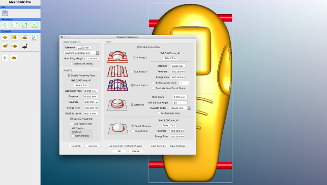
MeshCAM is driven from just a few dialogs, this being the predominant one
With this trend comes a corresponding need for CAM systems that allow you to take your 3D geometry and programme it for cutting in your desired material. The issue here is that, while the price of CNC machines may have dropped, the same can’t really be said for many CAM tools.
There’s also a second issue to consider: most CAM applications are built to meet the needs of users who are looking to create optimised toolpaths for final parts, intended for production, in the shortest time possible.
But if you’re doing prototyping work and just want to grab a chunk of model board and rip out a concept model, the functionality that these high-end applications offer is overkill in many respects.
This is where a system like MeshCAM comes into its own. Developed by GRZ Software, it’s become a favourite among users running affordable CNCs, for a few reasons. The first is cost: MeshCAM pricing starts at $250 for a perpetual licence.
Second, it’s cross-platform, working on both Windows and Apple OSX.
But above all, and unlike many production-oriented CAM systems, it’s geared to deliver in ways that don’t automatically come to light straight away — so let’s take a look at how it works and why we think MeshCAM’s a solid bet.
MeshCAM – Model set-up
The MeshCAM user interface is pretty sparse.
Almost all of the operations and commands are driven from a smattering of icons positioned on the left-hand side, which the user works through sequentially.
The first step is to load in your model. MeshCAM only works with STL data, so you’ll need to ensure that your part is output at the highest resolution your CAD system can manage.
As you import that part, the system will ask about the type of job you’ve got planned. MeshCAM supports 3-axis cutting, 4-axis if you have a rotary axis on your machine, and two-sided cutting.
While the process of setting up 3- and 4-axis jobs is pretty self-explanatory, two-sided machining is a little more involved, particularly if you’ve not done this type of work before.
Essentially, you’ll need to develop a set of toolpaths that will allow you to first cut one side of the part, flip it over and then machine the other side.
Accurate alignment of the process is vital, but once you master the quirks and get your machine set up with solid fixtures that allow you to reposition your part accurately and consistently, it makes the production of complex concept models a breeze.
MeshCAM also offers built-in tools to assist with scaling a part if you get a mix-up with units (that said, our own parts loaded perfectly). There are also commands to rotate, move and slice parts, the last of these being useful for getting parts into a smaller bed or with limited Z travel.
Next comes the process of adding in supports and this is crucial. Lower cost CNC machines tend to rely on clamps, rather than the workholding approaches you’ll find with more advanced, production-focused mills. As a result, it’s common to have a part self-supporting inside the stock.
MeshCAM enables you to position your supports, which connect the part to the stock, and retain the part as it’s cut.
You specify the size and it’s a case of finding the right balance between overly large supports (which will need removing) and too-small supports (which may fail to hold the part in place).
You’ll also need to position the supports in a way that makes finishing your part easy. Situating them on planar, or at least larger, surfaces is considered good practice here.
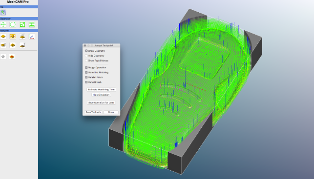
MeshCAM includes toolpath visualisation and machining process simulation, so you can run a preview, tweak settings and get the best results
MeshCAM – Machining parameters
The next few steps centre on defining the machining parameters for your part. First, you’ll need to figure out the retract height (the safe distance above the part to which the cutter will retract between each pass.)
Then, you’ll be digging into speeds and feeds – and it’s here that MeshCAM really displays its strength in handling the kind of work we’re discussing.
Essentially, you’re looking to define a set of toolpaths that will machine your part, but most lower-end CNC machines don’t offer automatic tool changes or even depth probes, so changing cutters between operations can lead to errors, particularly in setting tool length.
With MeshCAM, it’s possible to set up your cutter, then define a series of operations that will rough out your part efficiently, by removing larger quantities of material at first and then dialling down to focus on finer details with a series of finishing passes.
The part we’ve shown in the workflow below, for example, was cut using just a 3mm ball-nose mill.
The system allows you to define toolpaths manually, setting up the parameters for each operation in a single dialogue (shown in the image above), or run the Automatic Toolpath Wizard, and let the system take the strain, automatically choosing the best operations for your geometry and then giving you back the toolpath.
Assuming that you’ve opted for a software configuration that includes them, MeshCAM also gives you machining simulation capabilities. These will give you a handy preview of how your part will finish up and allow you to adjust parameters where necessary.
The final step is post-processing of your job. This is always the ‘fun’ part, as those who have worked with this type of tool will attest. G-code might be considered a ‘standard’ language, but in practice, variations from machine to machine and controller to controller tend to mean that post-processors need a little tweaking here and there.
(For example, when we recently had an issue with the X-Carve machine installed in the DEVELOP3D workshop, insofar as the generic post-processor wasn’t able to turn on the spindle, a quick email to the right developer and a swift change of post soon got the problem sorted without too much inconvenience.)

To enlarge image click here
Conclusion
If your work involves you engaging with sophisticated CAM programming on a daily basis, then it’s likely that MeshCAM’s going to feel a little ‘bare bones’.
You certainly won’t get all the bells and whistles typically associated with feature-led operation creation.
But, on the plus side, there’s no huge overhead in terms of learning how to use the system. You load your geometry, define the cutting conditions and let the software work its magic.
In other words, this is a great place to start for those of you looking to take advantage of lower-cost CNC machine tools and in need of a CAM system that will help you make the most of that resource.
MeshCAM is a cost-effective solution, certainly, and the results speak for themselves.
| Product | MeshCAM |
|---|---|
| Company name | GRZ |
| Price | $250 to $600 |