

CADfix – 3D data translation isn’t the nightmare it once was, but there are still issues. We look at a system, which aims to solve data exchange woes and has recently started to explore some remarkably advanced workflows
If you have spent any time using 3D CAD in the last 20 years, the name CADfix will be a familiar one. The product was initially developed to help move data between formative 3D design systems. Those of us that are long enough in the tooth to remember those days will recall that, in the early 1990s, the IGES format was dominant, but massively problematic.
CADfix has had geometry defeaturing and abstraction tools for many years
CADfix was conceived to sit between two systems that needed to communicate and fix any of the numerous problems that you might encounter, whether that was invalid or incompatible entities, corrupt geometry, or mismatches in tolerances and precision of CAD systems. It quickly gained market traction.
In the intervening years, many of these problems have been overcome, through improvements in translation agreements at a native level (most vendors have interoperability agreements in place), through translation library providers, and by improvements to the standard formats themselves.
In response, CADfix expanded its remit to focus on the transfer of data between 3D CAD systems and simulation software.
In particular, it began to address the specific geometry handling that needs to happen between CAD systems and analysis applications, in order to ensure an efficient meshing process, with reduced lead times and more accurate results. Whether that’s improving geometry to gain a better mesh or simplification of geometry to make the process easier, there is now a whole set of tools that look to address the needs of the advanced simulation crowd.
What is clear is that while CADfix’s roots lie in dealing with a very task-specific focus, over the last 20 years, the company’s development team has constantly looked to evolve the system, to move onto new core challenges that have emerged in its customer base and to find new ways to employ its knowledge and expertise in data translation and fixing.
The end result of that work is clear: CADfix at Release 12 is an admirably complete toolbox for data translation, one that can solve routine issues found in data translation, but that has also found new ways to innovate and advance the state of the art. So shall we explore what it can do? Let’s begin with the stuff it has done for years, then move onto some of the new areas that the team behind this product has explored in more recent releases.
CADfix – CAD geometry fixing
CAD Geometry translation has undoubtedly become a lot easier in recent years – but there are still issues that can throw you off course. These include problematic geometry issues, which are typically caused by poor modelling (either as a result of system-generated results or user error) or by problems in the data translation process.
CADfix has had tools to address these issues for over two decades and will allow you to both identify and, of course, fix them.
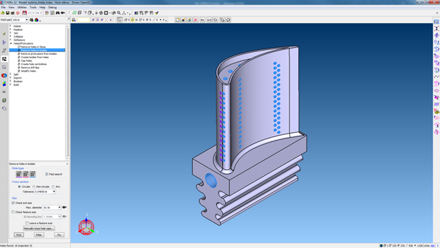
The system also includes a whole host of tools to help repurpose your CAD geometry for downstream applications, such as are found in manufacturing (such as mould/die design or CAM programming) and simulation. There are tools to help with removing explicit feature types such as holes, fillets, chamfers and so on, and for removing more complex feature or face sets, with the end result being a perfectly valid set of geometry.
It could be that you want to remove and cap off a set of pockets and holes that will be machined into a casting, for example, or remove all of the fillets on a cylinder head for thermal analysis. CADfix has tools that not only support you in performing these tasks manually, but also to automate such processes where appropriate.
The automation side of things is key. It moves CADfix from being a point solution that solves a very specific issue, to a much more useful tool in migration work that can relieve the user of the burden of performing a stack of repetitive processes.
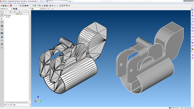
CADfix’s Back-to-CAD allows you to take a prismatic, tesselated part and reconstruct it back into solid geometry
CADfix – additive manufacturing
So far, we’ve talked about CADfix’s ability to work with CAD geometry, meaning typically analytic type geometry – the nice clean faces that you’d expect. In more recent years, the company has used its expertise with this type of geometry alongside meshbased data and started to explore the world of additive manufacturing.
The CADfix product now includes tools that not only ensure that you can preprocess your CAD geometry as you need to (perhaps using the same defeaturing tools we’ve already discussed), but also get your STL data output in the state that you require. That’s not something every vendor can guarantee.
Alongside these capabilities, there are also brand new tools that address additive workflows directly. One example is newly added support for more accurate slice data generation. One of the key differences here is that the slicing is based on curved facets, the issue being that very few CAD systems support the generation of data using this approach.
CADfix does, with the end result being that the curved triangles and resulting smooth slice profiles much better represent your intent.
Another area in which I see a lot of potential is the ability to generate a 3D model from slice data. Those that work with additive will know that the form you get out of a machine isn’t always the form that you have in your CAD system. For these layer-based processes, you’ll always end up with a stairstepped end result.
What CADfix allows you to do is take your CAD model, use its slicing tools to generate the slices at the size your machine builds at, and then have the system reconstruct the end result as would, ideally, appear out of the machine.
This could be useful for a number of downstream process; one might be finding areas of overbuild for rest machining, for example, while another could be having a more accurate representation of your‘as-built’ part for fluid flow analysis.
To enlarge image click here
Back to CAD & reverse engineering
Thus far, we’ve talked about how CADfix works with the conversion of CAD geometry to other CAD formats and to mesh-based output. But there are other new tools being introduced into CADfix that take the interoperability in opposite direction, which the team has called ‘Back-to-CAD’. In short, these tools target any process where you have a mesh-based, tessellated format and want to rebuild a more traditional CAD geometry model from it.
The initial instance is where you have a meshed model of a part and need to have an analytic, b-rep style CAD model. Using the facetted model tools, the system can build you a proper NURBS or analytic-based CAD model in a few seconds. It’s truly remarkable.
This, as you might expect, works best with parts with prismatic, non-organic forms, but having seen the capability at work on a number of test data files, it’s remarkable how well it works on other jobs, too.
It’s also worth noting that this is also intended for mesh geometry built from CAD files (using formats like STL, JT, 3D PDF or other native meshbased formats), rather than that derived from reality-capture processes such as laser scanning or photogrammetry.
CADfix – advanced geometry morphing
The final area I want to look at is entirely fascinating. It centres on the use of simulation and CAD geometry.
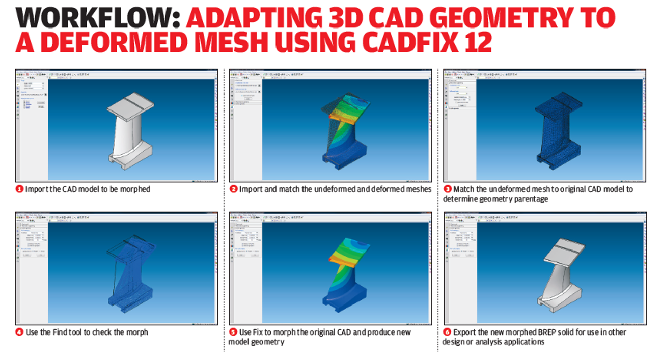
Consider how simulation is used: you start with a 3D CAD model and create a mesh for your simulation system. That mesh then has loads applied and you end up with a realistic representation of that part under those loads.
Now, what happens if you want to use that deformed shape in subsequent processes? Unless the subsequent process and systems can use the same mesh, you’re effectively stuck and looking at having to rebuild a model from scratch, or making approximations based on the deformed mesh data.
The new geometry morphing tool in CADfix allows you to take your original CAD model and mesh pair and use the deformed mesh as the reference to morph your CAD model to the deformed shape. The end result is a proper analytic CAD model, retaining the original face topology with morphed surfaces, that accurately represents your deformed shape – no remodelling, no conversion.
The applications for this kind of capability are many and wide-ranging, but in the end, they all come down to much the same thing: the benefits of having a clean CAD model of a deformed shape available, whether that’s to assist with modelling in process deformation of a part (compensating for deformation of parts under thermal stress during manufacture) or using a part deformed under structural or thermal loading in a subsequent fluid flow simulation (think of a wing in flight or a turbine blade in operation).
Of course, as with all such processes, there are some caveats, the main one being that if the simulation process adapts the mesh during the solve, it probably won’t work. That’s because the morphing operation needs to retain the exact same mesh, with node numbering and so on from the start to the end point.
In conclusion
I’ve always tended to think of CADfix as a tool that was developed to solve a specific set of problems, but one that gradually and quite sensibly expanded its remit as both the industry around it changed and new technologies became available. That point of view hasn’t changed at all since I last went to see the CADfix folks at their base just outside of Cambridge.
Today’s CADfix is a system that covers a wide range of bases and addresses a wide spread of issues around data translation, data repurposing and adaptation of geometry. In doing so, it is able to provide a good fit with an increasingly wide range of engineering processes.
That said, I can dimly recall describing CADfix as ‘the Swiss Army knife of data translation’. That was many years ago and the reality today is quite different. In fact, to repeat that trope would be to do CADfix a great disservice in terms of the advances it has made.
While the Swiss Army knife undoubtedly provides a great deal of functionality, the reality is often that its various widgets, blades, screwdrivers and whatnot all tend to be a bit substandard when they are compared to standalone tools, specifically engineered to perform a given task.
Instead, it’s far more accurate to think of CADfix as a set of tools that allow you to take your geometry and do what you need with it. The software can handle almost anything you can throw at it, from ensuring quality data translation through defeaturing, abstraction and automation into the realms of morphing and reverse engineering.
It does all of this with a single core tenet – that the data it produces is exactly as your intended downstream process needs.
So if you’re pushing the limitations of your current toolset’s data translation capabilities, and if issues frequently crop up, it’s definitely worth investigating what CADfix might be able do to help.
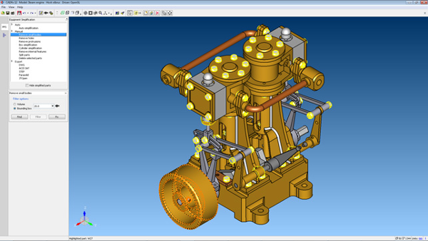
CADfix PPS is a stripped-back, ultratargeted application for the process and plant industry
While CADfix has always been known for providing a rich set of tools to accomplish some of the more esoteric and advanced workflows involved in 3D CAD use and simulation, the team there has also recently started to explore the potential to take its knowledge, expertise and existing tools and apply them to more specific, industry-focused applications.
The first is CADfix PPS, which stands for Plant and Process Simplification. As you might have guessed, the focus for CADfix PPS is taking datasets that are typical in the process plant world (which are massive) and providing a set of tools to help with simplification. Whereas CADfix has focussed on CAD repair, the focus for CADfix PPS is simplification of data.
Simplification in the process plant world comes down to taking heavy engineering models, reducing the complexity of the data they contain and making it more suitable for downstream use.
For example, the system can take an engineering model of some complex equipment, with a high level of detail, from a system like Inventor, which typically features 3,000 or so bodies and 140,000 faces inside a 800Mb STEP file, and reduce that down to a 29Mb STEP file with 500 bodies and 8,000 faces. That means the receiving system can get to work more efficiently and makes the data more portable, which can be important given that downstream users may be based in remote locations.
CADfix PPS does this by presenting a drastically stripped back interface that gives the user access to tools to quickly remove small parts (based on size), strip out unnecessary internal detail, simplify complex parts into bounding-box style representations and more, in order to achieve the data size and complexity reductions required.
Interestingly, there are also new data support options and workflows around some of the foibles of data translation methods involved in the process plant industry. For example, in some user communities FBX has become a standard for moving large, complex data around, so this now supported, along with more familiar formats including DWG, Parasolid, SAT, STEP and JT files.
It’s also worth noting that CADfix PPS offers the same potential for automation, so routine jobs can be automated, with more interactive sessions limited to where they’re actually needed.
| Product | CADfix 12 |
|---|---|
| Company name | ITI |
| Price | On request |


