With PTC Creo 4.0 moving to a longer release cycle, the flagship product now receives a big chunk of work for each major release. Here Al Dean looks over the latest updates to the legend that is Creo
When PTC announced in 2010 that it was rebranding Pro/Engineer (Pro/E) – its parametric, history-based modelling system introduced in 1988 – into Creo Parametric many wondered what the company could add to a tool that already had decades of development under its belt.
Creo is now on its fourth major release and the development hasn’t slowed down.

Creo’s interface has become a lot more responsive and connected. Shortcuts, based on your selection, present filter operations for that selection
However, the release cycle does seem to have stretched to between 18 and 24 months. For many organisations this is probably a good thing as it allows plenty of time to evaluate and prepare for upgrades.
So, let’s take a look at what PTC has in store for Creo 4.0.
Productivity improvements
As ever, there’s a wide range of updates and enhancements across all areas of Creo but, for the sake of this review, we’ll look at a few of the most widely applicable to all users and then delve into some of the more specialist updates that are of interest.
Perhaps the biggest update to Creo’s user experience can be found within the interface. While Creo went through something of a change during its transition from Pro/E to Pro/E Wildfire in 2003, the truth of the matter is that the system, at its core, didn’t change that much in terms of how you interact with it in general.
Yes, the user interface moved to a tab/ribbon-like appearance, but the fundamental controls didn’t alter that much or, indeed, get updated that often.
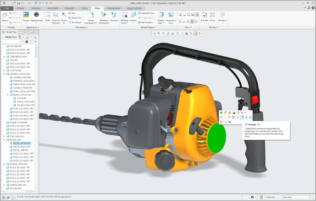
The Creo 4.0 release addresses some of this by introducing greater links between the model viewing and manipulation window and the feature history navigator, which weren’t particularly well connected up until now. Now, when you select a geometric entity, the system highlights the appropriate entry in the history listing and vice versa.
Alongside this, the development team has worked on making the whole process more interactive and context sensitive.
If you select an edge, a mini toolbar is immediately available providing options that apply to that edge such as fillet (round) or chamfer. The same is true of faces, parts and such. Each will provide a context sensitive toolbar (that can be customised to your requirements), so your reference to the toolbars will reduce and keep you focussed on the model.
At the same time, PTC has also introduced on-the-fly constraint selection and inference. This is most prevalent when building those all important feature sketches. Rather than carrying out a separate operation to add relationships or constraints, such items can now be quickly picked up at the cursor and added to the model, whether that’s end points, mid-points or centre points.
For those that are more experienced in other systems, this will seem a little late in the day — which is entirely the point.
In its early days, Pro/E led the pack before other systems over took it in terms of adoption. These systems are now used by students who use them to learn their modelling practices.
What PTC has realised is that it needed to upgrade Creo to meet these expectations. For instance, for those looking to bring new staff onboard who may have more experience elsewhere, these updates will help that process greatly.
Another interesting move that supports this is the ability to switch to a full screen mode. This pulls back the various toolbars and ribbons around the system and lets you focus on the modelling task at hand.
With the updates to context sensitive toolbars, you can work in this without reference to the full ribbons and toolbars. That said, if you need to, you can flick your mouse to the side at the top of the screen, and they’ll pop up long enough for you to find the operation you want, then disappear again.
Part mirroring is an area where PTC Creo 4.0 has upgraded in the functionality department
In terms of functionality updates, there are a ton of new enhancements to features and functions that have been in the system for quite some time. These typically extend the tools to make them either more efficient (by consolidating distinct workflows) or make those operations do more, more intelligently. An excellent example is the changes to the assembly mirroring tools.
Mirroring assemblies is a complex task that’s hidden behind a seemingly simple operation. Select the parts, select the mirror plane, done. The reality is much more complex. For instance, in many cases, you’ll need a mix of true mirrored parts, which are a reflection of the original across a plane, creating ‘handed’ components, and then parts that are simply copied across and assembled into the sub-system.
Most systems these days can handle this part, creating the mix of both handed components and instances where needed. That said, issues arise when you take into account very complex assemblies.
You might miss a part (or group of parts) that should just be simple instances of the same components, but instead end up creating another part number (or group of part numbers), which in turn leads to duplicates in the BOM, more stock parts (that are the same component, just referenced differently) – all of which adds up to cost.
What PTC has done is introduce a check when mirroring assemblies that looks at the geometry of all of the parts and decides whether you can reduce that part duplication automatically, and so reducing the odds of doubling up.
The system provides a preview and full control over the process, allowing you to know exactly what you’re going to get in the final assembly.
Complex shape design
While Creo (and its predecessors) built its reputation on parametric solid modelling, over the decades the system has developed into a set of tools that are used heavily in complex shape design.
While historically this type of work was done in a separate system (such as Alias or ICEM Surf), the Creo toolset (and Pro/E before it) has been widely adopted in many industries, with the benefit that a single system can more efficiently propagate changes in terms of styling or surfacing into engineering.
While base level Creo has a firm set of solid surface modelling tools, there are additional tools available in a couple of different modules. ISDX (or Interactive Surface Design eXtension) handles hybrid modelling (where surface modelling and solid modelling are mixed) as well as the more recently introduced FreeStyle capabilities, which brought sub-divisional modelling to the first release of Creo.
Let’s look at one of the highlight updates for both areas of the module’s capability.
Starting with more traditional solid/surfacing operations, it’s now possible to not only connect faces using G1 (tangency — where edges have a tangential connection across the join) and G2 (where surfaces connect and maintain curvature), but to define a G3 connection between faces (which provides curvature and acceleration — essentially, curvature that extends further into each surface).
Moving onto the sub divisional surface modelling tools in FreeStyle, this saw a lot of work over the last few releases and there’s a good selection of tools allowing you to build complex, organic shapes without the usual array of curves, surfaces and headaches.
What’s changed for this release is that it’s now possible to move data between sub divisional surface modelling systems, using the OBJ format.
This means that if your team (or indeed a partner or supplier) uses another system (such as MoI or Modo), then you can import the data using this format and have the system rebuild the surfaces based on the control points.
This allows for much more control and edit-ability.
PTC has replaced its existing renderer with a stripped back version of KeyShot, directly inside the interface
Visualisation with KeyShot
Although Creo 2 and 3 saw some work done on the Advanced Rendering Extension module for rendering inside the system (with the addition of HDRi driven environment lighting), the system was still showing its age, particularly when considering how things have advanced in recent years in the area of photo realistic visualisation.
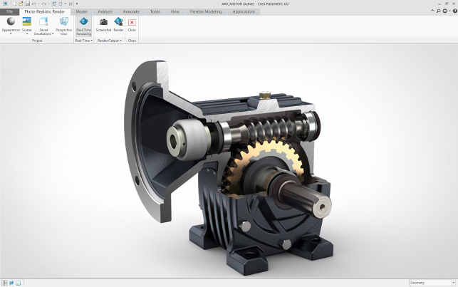
Instead of continuing to tweak the existing tools, PTC has done the smart thing and partnered up with Luxion and its KeyShot renderer.
Interestingly, instead of supplying users with a licence of the full KeyShot product, PTC has chosen to integrate the renderer directly into the Creo interface. This means that the new “render” option switches to the KeyShot renderer where the results ‘stream’ into the modelling window instantly.
It’s worth noting that the Creo implementation isn’t the same as the full blown, standalone KeyShot. There are some key differences. Firstly, the system uses the Creo camera controls (which aren’t the easiest to work). Secondly, and more importantly, the system uses a set of materials and environments that are linked to pre-set Creo materials, rather than using those within the full application.
The good news is that PTC and Luxion have chosen to keep some of the useful options and variables. Perhaps the biggest of these is the ability to limit the cores that KeyShot uses. If you let KeyShot use all of your system resources and CPU cycles, the machine will lock up until it’s complete.
With the CPU/core limiter in place, it’s possible to have KeyShot computing a render while you continue to work on another model or task — without having the machine die on its arse.
Of course, Creo users are amongst a large set of KeyShot users already — if you have a licence in place, you can export to it for further work. However, it is a shame that Luxion hasn’t implemented its LiveLinking technology for the plug-in yet. This means that any changes made inside Creo will have to be manually propagated to full KeyShot.
Creo 4.0 – Materials intelligence
Another update that is worthy of a little discussion relates to not only Creo Simulate, but also to that of collecting as much information about a part or product as possible during the design phase so that it can be reused downstream.
Many design systems allow you to define a physical material for each part in an assembly — how else would you be able to do massing studies, work centres of gravity and such?
Creo is the same, but for the 4.0 release it has teamed up with material specialist Granta Design to include 100 or so of its most common engineering materials.
This provides a comprehensive list of mechanical, thermal and electrical properties of each, directly from Granta’s massive database. That means that you’ve got industry leading materials data that can not only prove beneficial in design, but can also then be used in simulation tasks and even be extracted into Windchill and other MRP or ERP systems downstream.
Of course, if your chosen material isn’t supplied, you have other options. To enter them manually, you can buy the material data you want from Granta or, if your organisation has a Granta Design MI licence, there’s a plug-in that will allow you to access the full database directly.
Now, let’s move on to look at some of the brand spanking new additions for Creo 4.0.
These come down to three separate areas of focus, so we’ll look at them individually.
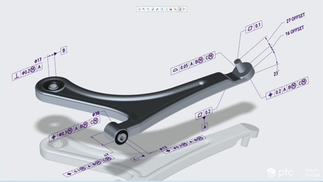
In Creo 4.0 users can fully annotate their parts
Creo 4.0 – Model-based design
First on this list is the work done to improve the capabilities for Model-based Definition (MBD).
Whether you call it 3D drawings, Product Manufacturing Information (PMI) or MBD, a move away from drawings as the primary source of critical documentation and annotation of a product’s manufacturing information and a move towards the model has been growing in acceptance in many larger scale industries, primarily automotive, aerospace and defence.
There are now several national and international standards in place, largely covered by ISO and AMSE. Alongside the formalisation into standards, recent updating of the STEP standard (AP 242 ) and standardisation of the JT format have meant that things are becoming much more mainstream.
PTC’s take on its PMI initiative has been to partner with Sigmetrix, a specialist in tolerance stack up analysis that has a healthy set of tools available for PMI creation.
PTC has taken its expertise and done some additional work inside Creo to make the whole thing work together. There’s a full set of GD&T (Geometric Dimensioning and Tolerancing) tools and they work intelligently inside the system, interacting with a model where needed allowing you to create the critical annotation to the standards required.
There are also checks in place and a lot of guidance (handy for those new to it), including filters that will not only allow you to apply annotations that are applicable to the selected geometry but it’ll also feedback on the completeness of your work, showing whether the model is unconstrained, partially or fully constrained.
Design for Additive Manufacturing is a focus for the Creo 4.0 release
Creo 4.0 – Design for additive manufacturing
The last area I want to touch on for Creo 4.0 relates to another hot topic at the moment, namely additive manufacturing.
Although it’s still in a period of exploration and research we’re starting to see greater acceptance of the idea of manufacturing components directly using sintering or metal pool machines as well as plastics-based processes.
What’s interesting is that many of the 3D design focussed vendors have finally realised that just having a couple of options for STL export isn’t going to cut the mustard and there’s potential for a much richer set of tools.
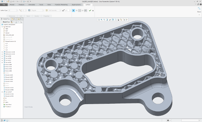
Building on the work started in its last release, Creo 4.0 covers both part preparation as well as design of basic lattices for light-weighting and optimisation.
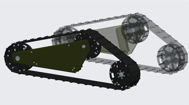
The lattice design tools follow a pretty standard workflow. Identify areas where mass can be safely removed or reduced in a part, then use built in tools to create a lattice work structure that retains the structural/mechanical performance of the part but reduces the mass.
PTC’s take on lattice design is as you would expect: you select the volume you want to convert, choose the parameters for the lattice (there are a range of pattern options, in fill options and such) then set the system to work. It’ll then create the lattice as per your requirements.
With parametrically controlled lattices, you can optimise them using simulation and also with the Behavioural Modelling Extension. The system handles the data efficiently (an issue in other systems working on such practices) and it can be taken into simulation studies to be verified and, of course, remains parametrically driven so design changes can be accommodated quickly.
The other group of additive manufacturing related tools are concerned with pre-processing of geometry for additive build or 3D print. Rather than just an STL preview and export, PTC’s tools provide a lot more. As well as a number of checks for printability across single parts, it then also allows you to create build platforms or chambers with automatic nesting tools, analysis for undercuts, preview of support requirements and much more.
The printability analysis is particularly strong, with checks for both thin walls and narrow gaps. While we’d all like our print processes to just build the design part, the fact is that some jiggery-pokery is often required to get a good result, particularly when you need to build scale models.
The system includes presets for a number of common machines from Stratasys (with 3D systems’ machine coming later on in the release cycle) that make the process less prone to error.
In conclusion
Creo has a rich heritage and the wealth of tools in the system wear that heritage on its sleeve. It’s also the reason that the system has retained, to date, some of the user interface quirks that, while perfect for the experienced users, would cause a bit of a barrier to those coming to the system from more modern tools.
This release sees PTC finally address this issue and update how the system works at a pretty core level, making it more intelligent and a lot more fluid when you’re deep in the modelling zone.
It’s also interesting that PTC seems to have realised that instead of redeveloping a set of tools, it’s better to work with partners that already have both the technology and the experience in those specific functions and, as such, this release sees it partnering with Granta Design, Luxion KeyShot and Sigmetrix.
The integration of the KeyShot rendering engine within the Creo interface is a smart move.
While many in the industrial design world already use Creo and KeyShot to great effect, the ability for everyone (with the appropriate module in place) to be able to create a render and then leave the heavy work (for the marketing shots and animation) to the specialists, makes huge sense.
The same goes for MBD tools. Why try and reinvent the tools when the standards are established and Sigmetrix has the knowledge and tech to fulfil them both robustly in terms of standards support and intelligence?
Elsewhere the expansion into areas such as Design for Additive Manufacturing is a similarly robust solution. It’s not just a tick box to say that “We like 3D printing”, these tools can benefit the process, ensure data is ready and explore the potential for things like light-weighting with lattice design, more easily and in an integrated manner.
Then there’s the forthcoming addition of Creo Product Insight, which connects PTC’s traditional CAD focussed business with its new moves into the Internet of Things.
All in all, Creo 4.0 is a solid release and one that’s going to provide benefit, both in terms of greater usability and new functionality, to every user and perhaps attract a new set of users that are looking to do more with their design and engineering.
Design for IOT: Connecting Creo to ThingWorx
In recent years PTC has been moving into the Internet of Things (IoT) space and if you’ve been following its progress you’ll know that it’s going at it all guns blazing.
The investment levels are in the region of a half a billion and the product stack is coming together nicely. What’s interesting is that PTC is clearly focussing on the potential benefits of linking user’s products to sensors, then feeding that information back to base.
Whether that’s at the customer’s site (for in field monitoring) or at the manufacturer, to predict service requirements.
Another interesting concept that PTC has been promoting is the Digital Twin, whereby the CAD model can be linked to a physical product.
There are many use cases here. At the prototype stage, the CAD model could be used to monitor a prototype under test, data collected, then used to drive further refinement (imagine having real world, instantly reusable performance inputs into simulation studies).
Another use case is to log information across a whole fleet of products, normalise and rationalise that data and, again, find trends and information from the real world that can drive design.
Of course, another might be post-failure. If a product is traced and logged when failure occurs, there is now a record of how it was used, what conditions the failure happened in etc.
But, for the majority, this has been discussed as a concept — the tools to do it haven’t been formalised into a product (in terms of hardware/software) to date.
This will change during the Creo 4.0 release cycle with the introduction of Creo Product Insight (it’s slated for a maintenance release later in 2017).
Creo Product Insight is the first delivery of a mechanism to connect your Creo model and its parameters and variables to a ThingWorx set-up.
ThingWorx is PTC’s platform for collecting and processing IoT data. Essentially, it’s a graphic system that allows you to connect to sensors in the field and collect their output.
What Creo Product Insight enables is a bi-directional communication stream between that digital model we’re all familiar with and the IoT system, and the use cases are wide and varied.
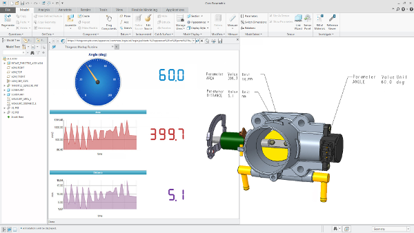
The bi-directionality is interesting because there’s potential to have loop-like feedback between information derived from sensors on a product and data calculated in Creo. Variables from one can drive the other. Imagine a product that is flagged up as performing outside of its operating limits.
A Creo session could be used to extract the use data, be processed (in an automated manner), fatigue simulation performed to find out how long until failure and then the customer warned.
Imagine a product under test. Information could be fed directly into the Creo model, calculations performed on the geometry and items that typically couldn’t be measured in the real world, fed back into the ThingWorx environment. Think Centre of Gravity as an example – and uses for further monitoring.
The potential for this is huge and we’ll be exploring it more when it becomes available (remember: it won’t be available at launch, but will come later in the release cycle).
PTC has been talking about this technology for some time, it’s good to see it finally make the product. Let’s see what its community does with it.
| Product | Creo 4.0 |
|---|---|
| Company name | PTC |
| Price | on application |