NX 12 – We begin a two part look at where things stand with the NX 12 release of the tool of choice at some of the most advanced organisations on the planet
Siemens PLM Software’s NX system is arguably one of the leading systems currently available for the design, engineering and manufacture of some of the most complex products available today – whether that’s aero turbine engines, cars or the smart phone in your pocket.
NX 12 includes a raft of additive focussed tools for topology optimisation as well as lattice design
While the system’s breadth and depth of functionality is the result of the combined development of both Unigraphics and I-deas (both of which date back to the late ’80s), recent years have proven that, while its capability is well established, the development team is still finding room for innovation and new thinking.
For instance, the system has led the development of synchronous technology, introduced freeform sub divisional modelling and, most recently, launched Convergent Modelling.
This brought Siemens’ geometric modelling expertise (remember that it developed Parasolid, the core of many of today’s modelling systems) to bear on integrating facetted and mesh forms alongside the more traditional surface and solid modelling geometry.
This provided the foundation for the incorporation of other tools, including an expansion of existing tools for working with mesh as well as topology optimisation (based on Frustum’s Generate engine, which we covered last month).
Of course, with its user community using this system to solve some truly gargantuan design and engineering problems, there is also a drive to enable them to work more intelligently, more efficiently and to allow the diverse teams involved into today’s products to work in a more connected manner. So shall we dive into the updates made to NX 12 and see where things stand?
NX 12 – Convergent modelling + working meshes
Let’s start with the updates made to NX focusing on the use of mesh-based data with the Convergent modelling technology.
While NX 11 introduced these tools and brought the ability to have mesh data alongside your standard solid and surface geometry, the NX 12 release extends this with a new set of polygon modelling tools.
These, in the first instance, provide you with tools to repair and repurpose your mesh data.
Whether that’s finding, removing and patching over the type of errors thrown up by laser scanning processes, fixing good, but unwanted data from a scan or, indeed, repurposing data acquired through other means. These tools are both an extension of the tools already inside NX as well as some new tools.
One of the key updates focusses on selecting and manipulating meshes and their constituent faces — which traditional box selects found in most CAD systems don’t lend themselves toward. With NX 12, you’ve got a whole bunch of selection tools, from lasso to a couple of different brushes, even flood fill to quick capture an area of geometry. These are much better suited to the process and complement the existing tools nicely.
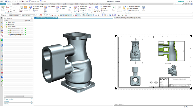
New to NX 12 is the ability to document convergent geometry. While you might not be able to add full dimensions, it’ll prove useful for integrating additively built forms into your documentation processes
Another new tool in this area is an automated mesh checking tool that will look for common faults and offers automated fixing — or you can dive in and fix those really problematic problems with the tools available.
Speaking of which, these allow you to patch, smooth out, reshape and correct your mesh geometry. Patching has options you’d expect, from flat, planar patching to curvature matching to surround geometry. The Smoothing tools will adjust your mesh in selected areas to remove those ripples or spikes that are often found at the point where scan data sets meet. There are also a range of tools to identify and modify bends in parts.
Using a colour-coding approach, it’s possible to identify edges (rounded or sharp) and then use NX’s tools to remesh those selections to your requirements.
What these all add up to is an environment in which you can adapt the mesh to your needs (whatever the source or the end goal), without having to go through a lengthy and often entirely unneeded remodelling exercise to reconstruct your mesh using traditional solid or surface features.
div>
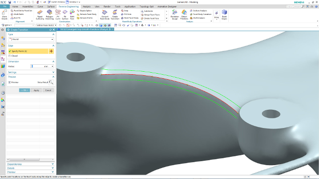
Adding a blend to a mesh’s edge. Not witchcraft, but convergent modelling
Once you’ve got your mesh in a fit state, then you might want to do something useful with it, perhaps start to add in engineering features or flesh out those smaller features.
Previously you were able to then start adding bosses, holes and cut outs to your mesh data. While the end result was always a convergent mesh, the system stored these edits as parametric, editable features so they could be adapted and edited when needed.
For NX 12, Siemens has extended these tools with a couple of new operations, the most interesting of which is the ‘Create Transition’ operation — and its use differs slightly.
To make use of it, you need to enter polygon modelling mode. This steps you back to the original mesh and allows you to add in features such as blends/fillets or chamfers where needed. The system looks for points of sharp curvature change (essentially, an edge) and allows you to throw in the radius or chamfer you need.
Adding a fillet to a mesh might sound like witchcraft, but this works, and works well, with the control you need.
Granted, we’re talking about single dimensional features (no multi-radii blends yet), but it’s a start. Once it’s done, and you exit polygon modelling mode, the system then reapplies your subsequent features.
NX 12 – topology optimisation
Those that have been paying attention will know that both of Siemens’ design focused systems, NX and Solid Edge, have recently seen the introduction of Frustum’s topology optimisation technology (you can read about Frustum’s cloud-based product, Generate, in last month’s issue).
NX got it first, so it’s now on the second iteration and it’s good to see that the CAD integrated flavour of it is keeping up with Frustum’s developments.
You’ve now got a few more loading conditions to apply to your model (most notably, allowing you to apply a torque) and greater controls over your form.
While the initial release had symmetry, you now have controls to specify no enclosed voids in the end result or to use an extrusion vector, which is really interesting when you apply this type of technology to machined components.
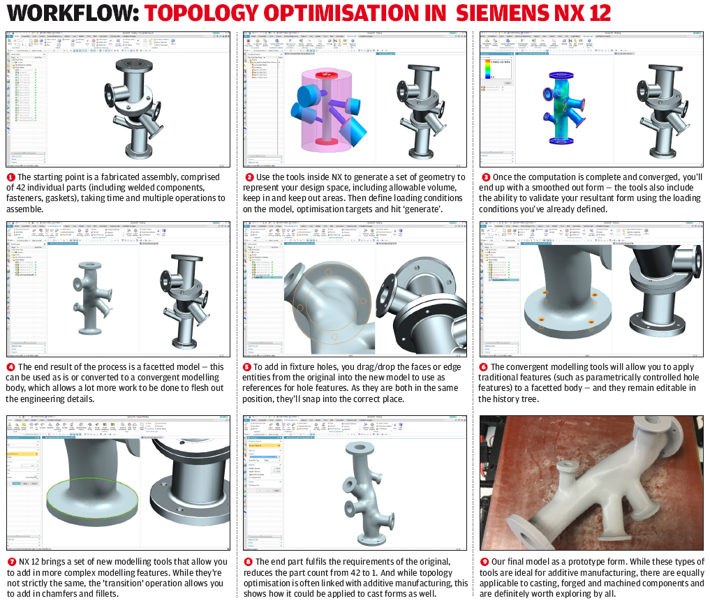
This last point is something that’s key: The software vendors are always keen to link this type of technology to additive manufacturing, but the reality is that topology optimisation can give you novel and efficient forms that can also be used in a wide variety of other production processes, whether that’s moulding, machining or, as in our case on the previous page, casting.
Of course, the real benefit of NX’s implementation is that it’s backed up with the convergent modelling technology. This allows you to take the mesh result from an optimisation study and start to add in the engineering features and detailing you need. The updates made in this release make that easier and more efficient.
One such update we haven’t already covered is the ability to ‘expand’ portions of a mesh. Topology optimisation can result in some unconventional shapes, which feature branch like supports between large portions of mesh.
While these might mathematically solve your load cases, experience and good judgement might mean you want to beef things up a bit – particularly as there are no controls over minimum spar or section size.
The new mesh offset tool allows you to select those spars, give them an offset value and have the system inflate those forms to provide more robust geometry.
To enlarge this workflow click here
NX 12 – lattice design
Now let’s look at a brand new chunk of code that addresses another additive manufacturing focussed update, namely lattice design.
For those that aren’t familiar with the use of lattices in the engineering world, the greater focus on additive manufacturing has seen a raft of effort being put into making the design of micro structured materials easier and more accessible.
Lattices are an engineering marvel and while there’s little readily available and easy to digest information about their benefits and how to go about designing them, there are a few key points to understand.
One of them being that lattice design is a complex game. It’s not a simple case of choosing a section of your part with which to fill with lattice structures, rather than solid material. Each instance needs to be understood, the operating conditions defined and the best approach selected
It is a highly formative sector of engineering design and one that’s undergoing huge research and implementation analysis. So, while you might be aware that there’s potential for saving mass or the ability to enable special characteristics in your parts, you can’t just dive in.
That said, once you have a good understanding of what you need to achieve, the tools with NX allow you to start to design those lattice forms easily. Existing users might be aware that lattice design tools were first introduced in the 11.2 release, but these have been worked on for this release, so we’ll cover them as if brand new.
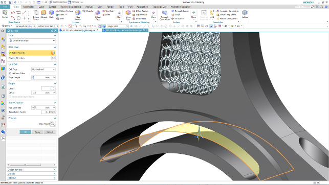
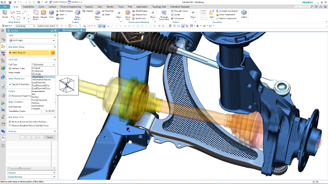
The lattice create tools will fill a volume in a linear manner (Unit Graph) or Conformal which follows a reference face
Essentially, NX’s tools allow you to select a portion of a part’s form (whether a void or a body of geometry) and fill that space with a lattice. NX has developed these tools with Belgian masters of all things additive manufacturing, Materialise, so there’s some good pedigree to this technology. The workflow works like this.
Start with your void you want to fill (driven by face selections), then choose the style of lattice. The options are either a unit graph or a conformal lattice. A unit graph creates a structural lattice that’s straightforward.
It’ll fill your space with a uniform lattice of your chosen cell type (more on those in a moment). A Conformal lattice allows you to choose the outer boundaries of your void, then a single surface to guide that lattice’s creation.
Next you need to define the cell style. Lattices use a singular cell which is repeated throughout the design space to create that intricate form. There are 8 or so options available and NX’s tools feature them all. Your choice of the form of your lattice cell will depend on what you’re looking to achieve and we don’t have enough room to detail all those options here.
You then define the starting point for the lattice with a single cell. By default, this is placed at the centroid of mass of that void you’re filling. You then define the dimensional requirements — how big the cell is and how large the connecting spars (referred to as rods in this instance).
NX then calculates the repetition of that single cell to fill the void you’ve defined. There are additional options to assist with over building and trimming back your lattice, so that you have good connections with the regular bodies in the part.
This is then created as a convergent body representing your lattice in position. There are some key points to note here. Lattices can be incredibly complex forms and trying to represent them with traditional CAD geometry would be almost impossible – a mesh-based form is the only way to go.
Hence, the result is a convergent body. That means you can apply subsequent operations to it (perhaps adding in additional detail), yet it’s also worth noting that, at present this is a one-hit-wonder. Once the lattice is built, you can’t edit it at all. You’ll need to delete it and start again.
Design checkers for AM
The last update related to both additive and convergent modelling I want to talk about is the introduction of new design checkers that look at your parts and make basic checks against several common additive manufacturing related errors or common problems.
Design checkers are found throughout NX and are used to add quality checks of your data, whether that’s 3D geometry and topology quality, drawing creation or something else.
The wall thickness check looks for areas where minimum wall thickness might cause build issues, which can be problematic with quite a few build processes. It also looks for wholly enclosed volumes or internal voids in your part — these can also cause several issues.
In metal builds, you could be trapping valuable powder, whereas in resin based builds, you won’t be able to extract that uncured resin (and in extreme cases, it’ll make your models pop like a lightbulb).
The check highlights them and lets you handle them before they’re sent off to build. The last two are self-explanatory, covering both overhand angle (identifying where you’ll need supports on both UV resin and filament based systems) and printable volume (to make sure your part fits on your printer).
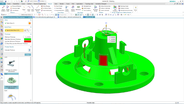
NX 12 includes checks against common additive manufacturing and 3D printing errors, including overhang and wall thickness analysis
In conclusion
Each NX release always covers a wide range of industries and process specific tasks. It’s also pretty robust in terms of stability, evidenced by an interesting fact that came up during a discussion of how quickly users adopt each release.
Daimler (which switched to NX from Catia some time ago) took on board the last release (NX 11) within four months — and considering that’s across 6,000 or so users, that’s a pretty good testimonial.
Here, we’ve taken a look at the updates to Convergent Modelling and a growing set of tools to leverage the ability to work with both traditional solid surfaces and solids alongside mesh geometry. This, of course, leads into topology optimisation, reverse engineering and additive manufacturing.
This heady combination is directly addressing an area that is gaining interest in many industries – and particularly in those industry sectors in which NX is strong (aerospace, automotive and medical) – but focussing purely on additive workflows would do it a disservice.
The simple fact that there’s now better handling of mesh-based geometry is going to be useful to a good slice of NX’s user community.
In the next part of our review of NX 12, we’ll dive into other areas of NX 12. These range from a set of animation design tools that runs from conceptual to fuller rigid body dynamics, to new updates to sheet metal design that let users rip through part creation and allows them to build multiple features in a single operation.
There has also been a good deal of work done in terms of multi-disciplinary design. This includes both new tools for P&ID, as well as mechanical/electrical/electronic tools, which should come as no surprise considering Siemens PLM’s recent acquisition of Mentor Graphics.
So next we’ll dig into these and more, and then conclude by looking at NX’s future direction.
| Product | NX 12 |
|---|---|
| Company name | Siemens PLM Software |
| Price | On Application |