

Siemens NX 12 – Siemens’ NX is the design and engineering tool of choice at some of the most advanced organisations on the planet, so any release is always interesting. Following on from last month, Al Dean completes his two part look at where things stand with NX 12
Siemens PLM Software’s NX system is arguably one of the leading systems currently available for the design, engineering and manufacture of some of the most complex products available today – whether that’s aero turbine engines, cars or the smart phone in your pocket.
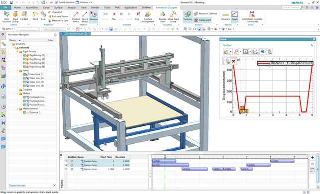
Animation Designer analysing the movement of a robot picker from a conveyer showing the timeline mode
While the system’s breadth and depth of functionality is the result of the combined development of both Unigraphics and I-deas (both of which date back to the late 80s), recent years have proven that, while its capability is well established, the development team is still fi nding room for innovation and new thinking.
For instance, the system has led the development of synchronous technology, introduced freeform sub divisional modelling and, most recently, launched Convergent Modelling.
This brought Siemens’ geometric modelling expertise (remember that it developed Parasolid, the core of many of today’s modelling systems) to bear on integrating facetted and mesh forms alongside the more traditional surface and solid modelling geometry.
This provided the foundation for the incorporation of other tools, including an expansion of existing tools for working with mesh as well as topology optimisation (based on Frustum’s Generate engine, which we covered in the October issue).
Of course, with its user community using this system to solve some truly gargantuan design and engineering problems, there is also a drive to enable them to work more intelligently, more efficiently and to allow the diverse teams to work in a more connected manner. So shall we dive into the updates made to NX 12 and see where things stand?
Siemwns NX 12 – NX Animation Designer
Let’s move away from convergent and additive design and look at more common or garden engineering tasks.
One area that has seen a big focus for the Siemens NX 12 release is the concept design of mechanisms and assemblies. While NX has had, for years, if not a decade, both basic assembly design and test tools (in terms of dragging linked assembly around) at the low-end and a fully blown motion simulation module (NX Motion) at the high-end, there hasn’t been much in between to help those that are looking to develop more complex assemblies from scratch.
This is the goal of NX Animation Designer, a name which perhaps hides its true purpose. It’s not so much about animation, but rather giving you tools to carry out, experiment and conduct both 2D and 3D free body motion studies, but without the overhead of the full blown NX Motion tool.
At the very earliest stages, this new module allows you to scheme out an assembly of parts using very basic geometry — we’re talking, lines, circles, arcs and splines. These can be connected to form the basic structure of parts with joints and relationships added. It includes a good selection of mechanical contact methods and assembly basics, including prebuilt templates for gears, chain and belts, rack and pinion and mechanical cams.
With regards to the availability of more fully defined 3D geometric parts, the system comes into its own when you’re looking to conduct quick motion checks with complex assemblies, particularly if the assembly structure doesn’t lend itself to such work. It’s often the case that you build and develop a complex assembly of parts and sub-assemblies in a static position.
Often you don’t necessarily need or want to disrupt those key relationships by moving your assembly, and with Animation Designer you can create assemblies and move them entirely independently of the design focussed structure. Of course, if you’ve already got your assembly structure ready for motion simulation and experimentation, there’s also an operation that will convert those joints into those suitable for motion simulation in an instant.
Whether you’re working with 2D geometry or full blown, engineering level models, you can gather more information from your assembly’s motion by adding in sensors.
These will give you graph-based outputs to show minimum/maximum conditions, which you can quickly snap to (and have the position of the constituent parts snap to the corresponding position).
It can also stop at collisions and interferences. The sensors are particularly interesting when you place one between two parts — this can give you a very quick idea of clearances and tolerance of closer contact parts.
Siemens NX 12 – Sheet metal design
NX Sheet Metal has had a wide range of capability for both basics and more specialist forming tools for a good long while. While the NX 11 release saw many of the more advanced tools consolidated into a more cohesive set of tools for auto and aero users, Siemens NX 12 has focussed on the basic tools for tab and flange to boost their productivity.
What’s interesting is that these tools are built from the ground up to get you a final sheet metal component in as few steps as possible. Although you might not see much benefit if you’re working on a smaller scale component, if you’re running a larger design team and working through clips and tabs in a product like a car, you most definitely would.
Driving this is a new multi-bend tab. Whereas traditional sheet metal modelling tools require that you build up a part tab and flange by tab and flange, with these tools you select all the faces (including any offsets) that you want to build off and the system gives you a single feature which includes multiple bends. You can then sketch out the exterior and any interior profiles, then finish. Job done.
Another update is the ability to build multiple flanges off multiple faces. While other systems might allow this, in the instance of NX, you have much greater control over each flange in terms of angle, length and radii.
There’s also been a neat little trick added to how NX handles the history of sheet metal parts and where the creation of the flat pattern occurs in that history, which traditionally would be right at the end of the process.
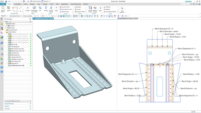
NX’s new sheet metal tools let you build complex parts more quickly and document more complex fabrication processes
From NX 12 onwards, you can shift the ‘flat pattern’ operation up the feature history. This means that you can apply operations that don’t appear in the flattened form (which is referenced in drawings) but the final folded form is accurate for assembly modelling. If you look at the image above, you’ll see that the flat pattern features two tabs at the bottom of the part, placed there to assist with making that tapered bend (and are cut off after the fact), but the 3D model shows the final folded form.
P&ID Designer
The final area we’re going to look at is a new module called P&ID Designer.
For those that aren’t involved in the industry, P&ID (Process & Instrumentation Diagram) is the process of developing routed pipe, valve and instrumentation in a wide range of industries, whether that’s shipbuilding, process plant or anything else.
NX’s tools are focussed on the marine industry but they’ll apply to many others.
It begins with the diagrammatic development of the parts within your system and how they’re connected. NX is supplied with a range of libraries, which hold a rich set of intelligent data. Of course, chances are you’ll look to develop your own where needed, but this is a pretty simple process. Place these, then start to connect them up — with inputs, outputs, runs and connections.
Once done, you use this diagram as the basis for then laying out your components in 3D space. Again, the system comes with a range of 3D libraries that are connected to those diagram components.
If your 3D components are fully defined, you’ll benefit from inference of things like pipe sizes. Of course, this is all cross linked. This means that when you begin the documentation process, you’ll be able to extract the information you need directly from the meta-data.
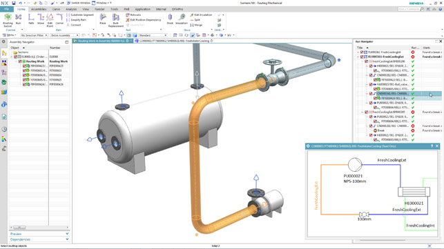
The new P&ID Designer module links together system-level diagramming with 3D part and pipe run layout
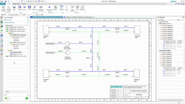
P&ID Designer detailing a simple system
In conclusion
Each NX release is always solid and covers a wide range of industries and process specific tasks.
Clearly, this release has focussed on the rise of design for additive manufacturing, which is gaining interest (if not immediate adoption) in many industries — and particularly in those industry sectors which NX is strong (aerospace, automotive and medical).
This is backed up with some core updates to the convergent modelling tools and additions to handling mesh-based geometry, which is going to be useful for a good slice of NX’s user community. The same is true of the NX Animation Designer, which I particularly like given the fact that it’s disconnected from the assembly structure.
Alongside these updates, the more industry sector focussed tools, such as P&ID and electrical/electronic integration following the acquisition of Mentor, show that the development team is looking to connect NX up with other technology in the Siemens portfolio — just as its customers are looking to do between their design teams.
In terms of Siemens NX 12, there’s more than enough here to satisfy existing customers. What’s interesting is that it’s a mix of breaking new ground, extension or advancement of existing tools, and looking to address a wide range of customer requirements.
NX is a broad system that covers the gamut of design and engineering requirements, from conceptual design (at both the aesthetic or mechanical level), through detail engineering and of course (which we haven’t covered in this review) a huge raft of manufacturing related tools.
With NX’s breadth of capability, you’d be forgiven for not expecting huge innovations, but the Siemens NX 12 release proves there’s still room to innovate and find new ground for rethinking how things are done.
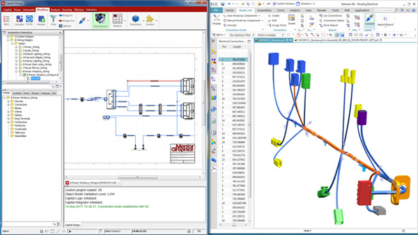
It’s now possible to connect Mentor Capital to NX data to allow a fully, richer and more accurate representation of harnesses to be developed in both systems
Siemens NX 12 & Mentor Graphics: Greater integration
Over the last few years, Siemens has been on one hell of an acquisition binge. From the likes of CD-Adapco through to the recently announced acquisition of electronics and electrical design giant, Mentor Graphics.
While we’ve yet to see the fruition of the CD-Adapco acquisition in the NX product range, there most certainly has been work done to integrate the workflow in Mentor’s tools with those in NX.
For the NX 12 release, this has been focussed on two key areas covering the bulk of the cross over between the two communities in many of Siemens’ larger customers.
Mentor Xpedition & NX Integration:
Xpedition is Mentor’s key enterprise grade PCB design system for electronics design. The new integration between this and NX allows not only integration of data from Xpedition directly into NX, but also a range of tools for cross probing and selection between the two systems, validation and mark-up.
What’s interesting is that while other such integrations between 3D design and PCB systems need to occur on the same workstation, within the world of NX, this can be achieved remotely.
Mentor Capital & NX Integration:
While Xpedition handles PCB design, Capital is Mentor’s system for harness design and when combined with NX, you have a very interesting set of tools.
You start with your logical representation diagram that sets out the connections between the various connectors in each harness.
At the same time, the various connectors can be placed in your NX model. Given correct naming conventions, it’s then possible to use the NX model to place connectors and route the harness through your model.
That, of course, gives you a wire length, which can be fed back into the Capital model, which then lets you work up your nail board drawings — all of which remains bi-directionally associative.
The control over this process is driven from Capital, as you would expect, with the harness design specialist pulling the required data from NX when needed.
| Product | NX 12 |
|---|---|
| Company name | Siemens |
| Price | on application |


