Solid Edge ST9 – As Siemens PLM’s mainstream design and engineering offering, Solid Edge has a reputation for robustness and reliability. We take a look at the latest release, which shows how innovation can be built into a 20 year old system
If you’ve not come across it, Solid Edge was one of a next breed of Windows-based 3D design systems first released in the late 1990s.
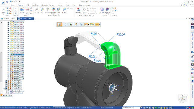
Fig.1 Solid Edge ST 9 allows you to preview features built after the current edit, irrespective of whether they’re synchronous or ordered
It has been built on top of Siemens’ own Parasolid kernel and where other vendors may have followed the latest trends, Solid Edge has remained consistent to its core values of enabling designers and engineers to develop, test and take products into production.
In the last few years the system has gained a boost in its profile (it never quite achieved the market mass of its peers) with the introduction of Synchronous Technology, which combined Solid Edge’s traditional history based modelling technology with direct editing of geometry and some clever intelligent filters/relationship detection.
The forthcoming Solid Edge ST 9 release is the ninth synchronous release since 2008.
Solid Edge & the cloud
One of the most interesting aspects of Solid Edge ST 9 doesn’t relate to the functionality and modelling tools in the system, but rather the environment in which they are used.
Siemens has looked to bring Solid Edge in line with how many of today’s users are working with the cloud. This isn’t a play to put the whole system in a browser, or indeed, a move to provide a different delivery model to a standard install.
It is about giving the user the choice to use the tools they need to work effectively where they need it.
So, let’s dig a little deeper into what we’ve got for Solid Edge ST 9 in this regard, with a focus on two areas.
The first is that your licence of Solid Edge can be made much more portable than before. While Siemens has always had the combination of node locked or floating licences, these are typically restricted to a single network or across a single organisation.
Now, it has provided a mechanism where individual users have a log-in, which gives them access to their licence where they need it. If you have two machines, say a desktop workstation and a laptop, you can install Solid Edge on both and the licence will follow you.
When you log-in, Solid Edge automatically pulls the licence to the current machine.
As soon as you exit Solid Edge, it reverts to the server, making it available. What’s also interesting is that the same action and infrastructure are also used to synchronise your settings (such as menus, UI configuration, customisations etc.), so they also follow you around.
The second part relates to using the cloud to make data more portable. Whereas some cloud-focussed systems require that all data is stored on their cloud infrastructure (Fusion 360 and Onshape for instance), the Solid Edge team is providing more freedom by allowing you to work effectively with your data in a shared, centralised environment using one of four big name hosting services; namely, Dropbox, Box, OneDrive or Google Drive.
At first glance, this doesn’t look particularly novel, after all, you could simply set-up your systems to store data on shared access drives like in the past — just as you could across a network.
The real difference relates to how Siemens has introduced some data management and access controls that would typically require a PDM solution directly into Solid Edge — specifically that allow locking of data during edits as well as other controls for versioning of parts, which we’ll come on to next.
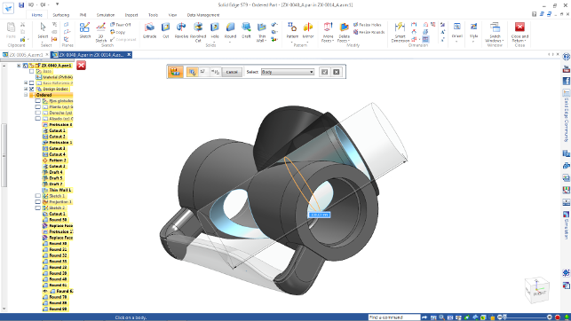
Fig. 2 Solid Edge ST 9 makes working with multi-bodies more flexible and closer matches the freedom of Synchronous Technology in that operations can span multiple bodies in one go
Solid Edge ST9 – data management
Over the last few years, the range of data management options for Solid Edge has changed.
The entry level took advantage of a CAD-focussed overlay on Microsoft’s SharePoint, which added in revision and some basic change management.
Then, at the other end of the spectrum, there is also a closer integration between Solid Edge and Siemens’ all singing, all dancing, larger enterprise focussed PLM solution, Teamcenter.
This still remains the case, with Solid Edge ST 9 also seeing greater integration between Edge and Teamcenter. It means much more of the typical interactions with the PLM environment are done directly inside Solid Edge, rather than stepping out to a Teamcenter client.
If you’re already familiar with Teamcenter, then knowing that Active Workspaces have been built into Solid Edge will give you a good idea of the level of integration.
This release also sees a new entrant at the lower end of the spectrum that is a step above standard file structure and folder data management, but isn’t quite as complex as using SharePoint.
Essentially, there are now instantaneous searches, easy revisions and release management, and optional cloud based vaulting directly inside Solid Edge that work on the raw file structure (both locally, across networked drives as well as cloud-based drives).
These include editing and lock-outs when a user is editing data as well as revision controls and automatic part numbering.
The system takes advantage of Windows’ Indexing to provide not only quick search tools, but also a means of quickly running them where used and used by searches with a CAD specific presentation of relationships. There’s no database set-up, it’s all built in.
There’s also a set of updates that have an infl uence on the flexibility of handling complex assemblies and common issues when working larger amounts of data across teams. This relates to the assignment of unique names to instances of what’s essentially, the same part, geometrically speaking.
Imagine an assembly that has 25 M8x25mm fasteners of some description.
While they would normally be the same part number and be referenced in the BOM as the same part, it might be the case that you want the same part geometry, but assign a unique ID to a portion of them (perhaps they’re a different colour, heat treatment or material).
This means that you can use the same geometry file, but assign unique IDs to those that need it. File count is lower, but you get the correct BOM.
Solid Edge ST9 – modelling updates
Let’s begin with the user interface which has been through some changes in the last few releases.
The current state of the art will be familiar in operation and look/feel to anyone that’s familiar with modern Microsoft office products — here, the ribbon is king.
While Siemens hasn’t changed a great deal, there has been some work done to make the system more effective when you use it on today’s increasingly common 4K displays.
You’ve also got tabbed documents, rather than separate windows, with a good set of tools to quickly close down the windows you don’t want.
Alongside this, there are a couple of ‘general’ user experience updates that will be worth taking note of, particularly for existing users.
These centre on showing the data you’re interested in and removing extraneous details. One of which is the new Toggle Display that will quickly make parts transparent and the Isolate tool will hide everything except the selected parts.
While the UI changes to be consistent with the current Microsoft guidelines, there are also some tools relating to both licensing and data management that has the potential to be of interest to almost everyone.
So, we’ll now take a look at the tools for design, rather than managing the data that’s a result of it.
If you’ve been following Solid Edge for a while, you’ll know that the system has two modes of working. Ordered is how the company talks about traditional history-based modelling tools that we’re all familiar with. A linear history of discreet features that are recorded and tracked to build up a model.
Then there’s Synchronous Technology, often reference to direct modelling, although that doesn’t quite do it justice.
Synchronous modelling techniques combine the idea of direct modelling (pushing, pulling and rotating faces) with the capture of dynamic relationships between geometric entities (such as tangency, parallelism etc.) to make the process more efficient and intelligent (Siemens call these Design Intent).
The difference is that Synchronous edits are typically one offs. You make them and you’re done. There’s no formal feature as such, apart from in specific instances like patterns. If you need to make another tweak, you just repeat the same operation, rather than editing an explicit feature.
What makes the situation more complex is that while there is a definite line between the two, there are often differing workflows between Ordering and Synchronous ways of working and your selection of the method depends on the end result you want and your need to edit it afterward.
It’s also the case that to accomplish some tasks, you might need to mix and match.
For this reason, there’s been work done to address this and establish more ‘hybrid’ workflows that take advantage of the benefits of both ways of working.
In the first instance, Siemens has addressed the separation of the two parts of a part’s construction history and not being able to see the effect of changes to, for example, Synchronous edits on downstream ‘ordered’ features.
It’s now possible to see a preview of the final result of both categories, rather than just the category of the parts of the history you’re working on.
For instance, Figure 1 shows an edit being made to a part in the Synchronous mode, but also shows the resultant downstream loft between those two parts, while you’re doing it.
There has also been work done relating to multi-body modelling techniques. It is an age old idea that you can build up a model using separate bodies within the same part file.
With the rise of direct editing and cloud-based computing, multi-body modelling has seen a rebirth of interest in recent releases from most vendors.
While Solid Edge has supported multibody modelling for many years in its traditional ordered mode, the workflow has been similarly traditional. You needed to activate and deactivate each body as you worked on it and features that spanned across multi-features were troublesome.
This complexity carried over into the multi-body tools when in Synchronous mode, but that doesn’t suit the more freeform nature of that way of working.
Solid Edge ST 9 fixes this and allows more freedom to create models using multiple bodies in Synchronous mode and carry out operations that span across several bodies, without worrying about which bodies it’s affecting.
It’s worth noting that multi-body support in ordered mode remains the same as it has been for a while, requiring activation and deactivation of individual bodies.
These updates also have an influence on other aspects of Synchronous modelling techniques. For example, it’s now possible to quickly pattern or mirror bodies within a single part fi le and these are persisted — that means that unlike more Synchronous Technology operations, the parameters are stored in the feature tree so can be edited.
Another feature that’s been added into the Synchronous Technology toolset relates to threaded forms. While we’re used to not actually modelling threads into a model, there are many cases where it’s required as hard geometry.
If you construct a thread, it’s now possible to use that feature as a reference during a Boolean and have the system automatically create the opposite thread form. While this doesn’t sound like a big deal, the fact that it’s not a simple Boolean, but rather respects the thread standards (for closeness of fit and tolerance etc.), gives you an idea of how useful it is.
There’s also a new capability that relates to building parts that reference existing surfaces, typically using a feature built with an offset from a surface. Previously, you would have needed to create several features to get to that start point. Now you can reference the surface and build out the feature directly — saving time and also making the inter-part references more efficient.
The last Synchronous Technology update we’ll cover relates to creating features that take references across geometry across an assembly. The first now lets you build a sheet metal contour flange using edge references from multiple parts (previously it would only work across a single part).
The second relates to making modifications to faces across an assembly using the “replace face” operation. Again, this would have involved editing each part’s faces individually. Now you can select all of them, select the reference face and — snap — it’s done.
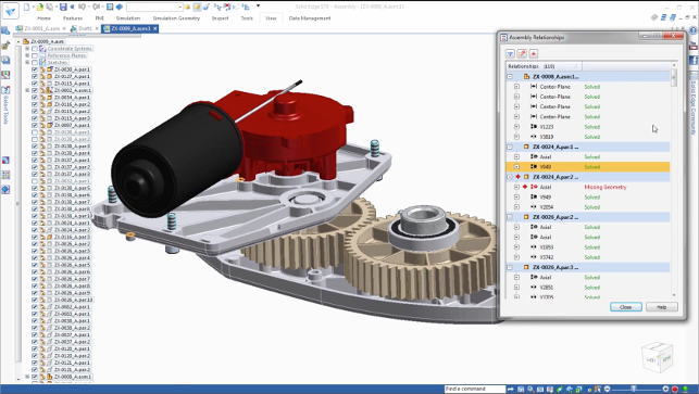
Fig. 3 The new Assembly Relationship manager gives you an instant understanding of inter part relationships in a part and highlights any issues — even snapping you to the problematic features for fixing
Solid Edge ST9 – ordered specific updates
While the bulk of the focus for Solid Edge ST 9 has been the evolution of Synchronous Technology, there are a couple of features that specifically relate to ordered ways of working.
Perhaps the most useful is the Solid Sweep operation. At first look, this appears very similar to the standard loft operation, where a 2D profile is lofted along a defined path, but it’s rather different.
The key difference is that rather than using a 2D sketch profile and a path, you’re using a 3D form along with a path. Imagine running a cutter along a path — the form will differ, however slightly, from using a 2D profile. The differences are subtle, but those that explore the options will no doubt find benefits from it — particularly if you’re looking to model in features such as cam followers or other more complex cut-outs in shafts.
It’s also worth noting that the SketchPoints are now available in the ordered environment and when combined with lofts or sweeps, they prove very useful, especially in instances where creating a point in space is difficult using traditional work-planes and sketches.
Enhancing older features
Another feature that’s clearly a trend based on an existing technology (that’s been around since the inception of CAD) is the greater use of co-ordinate systems.
Now in Solid Edge, you can define a number of co-ordinate systems which retain information about the alignment and position of the X, Y and Z axes.
These can then be used to build features off (using specific references to those co-ordinate systems’ 0,0,0 position) or used to drive other features — such as patterning.
If you paid attention to the ST 8 release, you’ll also know that it saw the introduction of the Duplicate operation.
This allowed the copying of a part across an assembly, where conditions allow (matching location features etc.). This has been extended to now allow the same to be done with a wider set of geometry as well as parts, including faces, features and simple selections of geometry.
It also provides greater control over how the part is duplicated and it’s now possible to adjust rotation at each instance. This can be driven by co-ordinate systems, sketch blocks or more traditional patterns.
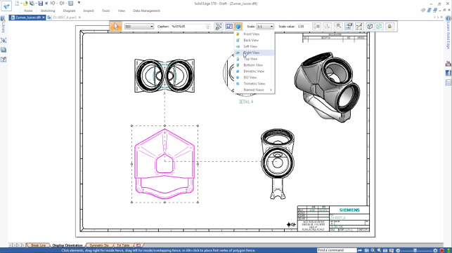
Fig. 4 No update is complete without updates to drawings. One update is the ability to rotate drawing views for optimum layout clarity
Managing complex assemblies
Considering Solid Edge’s success in the industrial automation field where assemblies are typically complex and highly inter-dependent in nature, the changes made to how the system handles assembly relationships are going to be a boon to many.
The new Assembly Relationship Manager provides you with a list of all of the relationships in your assembly in a single dialog. There are filtering tools to find those you’re looking for (by name, by type).
While, if your model is working, this won’t make much difference, if you make an edit and you find certain assembly relationships break, the same dialog is used to find issues and explore what’s wrong.
Then, with the click of the error, you’re not only presented with the geometry referenced, but also the system snaps you to the point in the assembly structure you need to fix that issue.
Conclusion
The cloud-related updates to Solid Edge are good news for those that, for instance, spend a lot of time with customers, on site, or with suppliers.
The ability to be able to access licensed software is critical and more often than not, falls down in instances where you haven’t planned for it. This saves you a lot of that effort.
Of course, it’s not the case that you can simply jump on any machine and start using Solid Edge quickly (the install still requires a hefty download), but this is better than nothing.
The closer integration between common cloud-based services is also good news.
Whether you prefer OneDrive to Box, Dropbox to Google Drive, the fact that you can quickly store your data there and have Solid Edge not interfere with it (which is common with other applications) in terms of synchronising as well as access/locking control, will benefit many — even if you don’t use it on a day-to-day basis.
Also interesting is how Siemens has continued one of the themes we identified in the ST 8 review, where the development is looking at long-existing processes and methods (in both Solid Edge and further afield) and making use of them once again or reinventing them.
One example of this is the use of coordinate systems. Those of us with greying hair will remember older generation systems made greater use of these for a wide variety of workflows, whether it was generation of features or location of assemblies.
Good to see it come back and be integrated into the patterning tools amongst a few others with Solid Edge ST 9.
All in all, Solid Edge ST 9 does what Siemens’ excels at in the mainstream — it manages to push forward its technology, while at the same time, reinventing or reusing old methods that have been around for decades in new and interesting ways.
Further reading & watching:
- Guide to keyboard shortcuts (YouTube)
- Assembly Management (YouTube)
- How Hall Design rips up the desert with Solid Edge (YouTube)
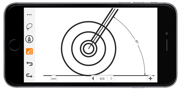
Sketch to vectors on your smart device? Yes please. And the good news is that it doesn’t break the bank either
Siemens heads to the app stores: Catchbook
Alongside the recent Solid Edge and NX releases, Siemens PLM has also just dipped its toe into the world of consumer focussed applications.
While it has had a number of apps for smart devices for Teamcenter for a while, Catchbook represents something of a departure for the development team.
Available for iOS, Windows and Android, Catchbook is a sketching application. While there are numerous iterations of this idea, Catchbook offers an alternative take. It does quick capture of ideas and overlaying over photos, but the real killer is the ‘drawing’ tool.
This takes your, inevitably dodgy, inputs, and quickly converts them into clean, crisp vector geometry. There’s automatic snapping between end points and quick identification of relationships (concentricity, parallelism).
It will also allow dimensions to be punched in when you have them. This means you can quickly sketch a shape, convert it to clean vectors, then get it into the correct size (the first dimension scales the whole sketch).
The app is free, but if you want to use the accurate vector tools — as well as if you want to export the data to SVG, PDF or DXF, you’ll have to pay up for an annual subscription.
A bundle for both is currently $5.99 a year, so it’s not like it breaks the bank.
That also means that you can bring that data into Solid Edge or, indeed, any other 3D CAD application.
To give it a whirl for 30 days for free (including the add-ons), search for ‘Catchbook’ in the app store of your device of choice.
| Product | Solid Edge ST9 |
|---|---|
| Company name | Solid Edge |
| Price | on application |