NX’s background lies in the merger of Unigraphics and I-deas back at the turn of the millennium. Since then, the Siemens PLM team have been working to not only extend and enhance the system’s capabilities, but to also bring the user experience up to date.
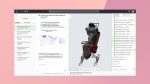
Fig 1. NX now has the ribbon. It’s clear, accessible and discoverable. And if you really want to, you can switch back to classic
The introduction of Synchronous Technology in 2008 gave the product a shot in the arm and helped to raise its profile. It did the company untold good (literally, as Siemens never discloses sales unit counts).
NX has grown in sophistication in the intervening years. Synchronous Technology has been increasingly integrated into the more traditional aspects of the system, while its workflows and processes have been ironed out and built upon.
So, if Siemens is flagging 9.0 as the most significant release since then, let’s explore exactly what backs up those claims.
Ribbon a-go-go
We’ll kick things off with the user interface (UI). NX (and prior to that, Unigraphics) has been through a lot of changes in the last five or so years.
The UI, as it stands now, is clean, polished and impressive by anyone’s standards. But (and there’s always a but) that UI is very specific to NX and, although Siemens has now adopted the now familiar ribbon style UI, I can imagine that long-term users will be throwing their arms up in frustration. However, stick with me on this.
Siemens has done a pretty solid job of easing this transition, which has been accomplished in a few ways.
The first is that all of the system’s commands, by default, have been arranged in tabs by process or workflow. That means all the tools needed for a specific job are available and ready to go.
The second is that it’s entirely customisable. Panels can now be added and commands switched in and out where needed. I’m sure most users will quickly adapt it to suit their most common workflows.
The third is that the Command Finder has been enhanced. While it’s been there for a while, it’s now directly within the UI. Now, you can tap in a search term and it’ll not only provide direct access to the help for that feature , but will show where it is.
Sketching gets sync tech
By now, we should all be aware of how Synchronous Technology works in the realm of geometry manipulation.
The ability to push, pull and generally wrangle geometry directly, without having to edit history, is something that’s become prevalent in many systems in one way or another. What differs in the NX world is how these tools are both intelligent (in terms of automatic detection of geometry conditions) and integrated into the existing tools.
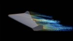
Fig 2. Synchronous Technology has been extended to allow editing of geometry using a dynamic cross section
While the Synchronous Technology tools for 3D geometry continue to mature and evolve with this release (we’ll get onto that shortly), there’s been a focus on introducing the same concepts to other areas of the system too — namely, sketching.
Imagine, if you will, that you’re working with those fundamental sketches that drive feature creation. You’ll be familiar with what happens when you drag and drop entities in a sketch that aren’t constrained.
Most systems include some sort of predictive constraints placement. But it’s often the case that doing so will result in a nightmare where tangency between lines and arcs will flip and other geometry will shift in an undesirable manner.
Synchronous Technology for sketching uses the same live relationship detection and management tools found in geometry manipulation, but in a sketching environment, with the Curve Finder.
Without explicitly having to apply constraints, the system will find areas of tangency, symmetry and such. While it’s subtle, the end result is being able to make edits to unconstrained geometry that are much more predictable.
It won’t remove the need to add those constraints, at the early stages of sketch layout, but it’ll be invaluable — particularly if your working methods are based on top down, sketch driven assembly design.
It’s also interesting to note that the same tools will work on imported 2D data, where the usual caveats of good clean geometry apply. This means that legacy drawings can be edited with the same tools and dimensions will update where needed.
Elsewhere in sketching, there are additional updates to a couple of operations that are worthy of note. One is how the system handles moving entities. Rather than pure move operations, you can now also offset them. Again, this is a subtle change/addition, but it gives more control when adapting geometry.
The same is true of the new edits to fillets in sketches. These can be done either from the centre of a pocket or by the centre of each fillet.
3D edits by cross section
Now that we’ve established what Siemens has added into sketching regarding Synchronous Technology, let’s explore how those same tools are available for use in the 3D environment.
They can now be used when working with a cross section placed through the part. Those that have seen or worked with SpaceClaim will be immediately familiar with this.
The concept is that when using direct editing, you edit a cross section of the part, rather than the faces and edges. This provides a couple of benefits. The first is that in some cases, the internal geometry of a part needs to be edited.
Fig 3. In addition to pushing and pulling faces, edges can now be manipulated with the system handling geometry adaptation
This isn’t necessarily the easiest thing to accomplish when direct editing faces. But by throwing a section through the part, you can grab the edges (created by the section) and move them into the position required.
What’s interesting is how this affects the geometry related to those ‘edges’. For example, manipulating a fillet in cross section mode will have the effect of changing the radius of that fillet directly attached to it (think: those that the cross section passes through).
What it won’t do is change any fillets that are subsequently connected to them (think: fillet chain around an edge). In fact, what NX does is convert the fillet chain into a variable radius fillet and handles the transition.
Of course, this might be your intent, so some additional work may be required, or you just edit that chain in a more traditional manner.
Other sync tech updates
With all these solid updates, you wouldn’t have thought that there would be any updates to the core modelling tools.
You’d be wrong as NX 9 sees the introduction of a handful of new workflows that look to solve very specific issues with geometry modification and preparation for manufacturing. So, let’s look at each.
Edge Edit: This is the ability to make synchronous edits to edges as well as faces. Once again, it’s subtle but that’s why it’s key. Instead of just moving a face lock, stock and barrel, this affords more control and allows interesting edits to be made.
A perfect use case is the ability to adapt draft in a very localised manner. Rather than trying to shift an entire face, this allows you to grab the edge at hand and shift it to add in the conditions needed.
It’s a seemingly small thing, but editing complex geometry in the tooling industry is a constant challenge which this addresses quickly and easily.
Blend Corner: This addresses the often poor quality geometry you see when running three or more fillets into a corner. The automated tools often give a result that, although geometrically correct, is less than pleasing, either from an aesthetic or a manufacturing point of view.
The Blend Corner allows you to select the fillets that run into the corner (either internally or externally) and adjust how that corner patch is created. It provides control over how each fillet runs into the corner, setback options and how it transitions.
It’s all done in a drag and drop manner, but specific values can be dialled in where needed. Again, it’s worth noting that this works for imported geometry as well as native.
When combined with the tools introduced in NX 8.5 to help with removing and redefining fillets (the Partial Fillet Delete in particular), this is going to be big news for a lot of users, whether preparing data for tool design or for industrial design.
Analyse & Fillet Pocket: These two operations are inextricably linked. The first, Analyse Pocket, gives a set of tools built into the Check Mate diagnostic tools, that allows you to grab a part, run a set of checks on it and find areas where machining might cause issues.
Its use requires a cutter (in terms of style and size) and machining method (such as 3-axis and 5-axis) to be defined. The base of the pocket is then selected.
The system then looks into the geometry and finds areas that are inaccessible by the defined tool and where there’s inclined faces, or inverse draft. As with all Check Mate tools, this analysis is live, can be reported on and automated if needed.
What’s interesting is how the Fillet Pocket operation can take advantage of it. Anyone that’s familiar with machining will know that constant fillets in a pocket is desirable, but often not defined by the user.
This operation takes the results of the pocket analysis and can adapt the fillet to account for the machining method. For example, if the pocket has slight inclined faces, the fillet will not only adapt the fillet and surrounding faces to account for this, but also ensure that the geometry matches the end result.
Fig 4. The new Check Mate integrated Analyse Pocket allows you to find areas of concern for machining
Figure 4 shows how this is applied to a pocket. The inclined face is adjusted, the fillet is added, and where the cutter can’t reach, the system adds a fillet that means it doesn’t have to.
The end part is an exact match for the result of the machining process. That means that not only is the digital model more accurate, but so is the massing and costing information.
It might not make a difference with a single part, but in an airframe context for example, there may be hundreds of these parts and that can have a significant effect on mass and CoG (centre of gravity).
Sub division surfaces
While so far we’ve looked at the evolution of existing tools, this next one is brand new for NX 9.
Those that have been watching the CAD industry for some time will know that Sub Division Modelling is gaining popularity and is being introduced into various systems. Some (PTC Creo and Autodesk Fusion 360) have native tools, others have plug-ins (Power Surfacing for SolidWorks) whilst others do it all on their own (Modo).
In the NX world, it’s definitely gone down the integrated track and NX 9 sees the first introduction of this type of technology in the Siemens portfolio.
All of the tools are found in the “Realize Shape” operation. This is a single feature tree entry that, when started, opens up all of the tools.
If you’re unfamiliar with Sub Division Modelling, the basics are that you start with a lump of geometry — in the case of NX, it’s a sphere, a box, a face — around which a control cage is added. You then begin to push/pull, rotate and scale that cage to pull the edges and vertices of the geometry it’s connected to.
The system handles all of the manipulation and the end result is a set of geometry that would be time consuming to model manually.
If you’re experienced with this type of methodology already, all of the tools are there as you would expect — bridging to connect faces, magnitude control and flattening faces.
While we don’t have room to dig into the details, let it be known that the state of the art in NX is pretty advanced and should satisfy many of those who’ve already tried this type of technology. But what’s most interesting is how it’s integrated with the other aspects of the system.
Unlike other tools (such as Fusion 360), there’s no need to convert the geometry from SubD to NURBS geometry. Instead you can immediately close that feature and start modelling on top of it, to it and around it. If you then edit that SubD geometry, the changes can be propagated through downstream features.
Conclusion
We’ve not had space to look at everything that’s new and improved in this NX release but this should give a flavour of what Siemens has been up to.
Siemens anounced NX 9 as the most significant release since the introduction of Synchronous Technology and judging by what I’ve experienced, I have to agree.
NX is a legendary system amongst designers and engineers at the cutting edge — whether in consumer product design, aerospace or automotive. That’s been the case for decades in one form or another.
What NX 9 shows is that maturity isn’t holding the team back from exploring new ideas and introducing new concepts, whilst evolving and enhancing that wealth of technology and capability already in the system.
The UI changes might be a sticking point for long-time users, but with tools that help make the system more discoverable without formal training, the transition should be easy.
| Product | NX 9 |
|---|---|
| Company name | Siemens PLM |
| Price | on application |