Amongst the heavyweight 3D design and manufacturing systems, there are those that grab the headlines; those that have a great deal of fuss made over their status in the world.
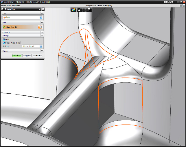
The new ‘delete partial blend’ command lets users work their way around deleting (and then rebuilding)complex fillet intersections
Then there’s Siemens PLM Software’s NX. The high-end system has been on the market for a good while now since the merger of the Unigraphics and I-deas product lines.
Since the initial release Siemens NX has changed greatly. While the underlying power of the two seed systems has been maintained, the last few years have seen it advance. The user interface now looks clean, fresh and understandable, even for the new user.
The introduction of Synchronous Technology brought new tools to the system, but rather than changing the use case as it did in Solid Edge, the NX implementation was more subtle and arguably more powerful.
It took the benefits of direct modelling but, instead of splitting it out, the Siemens NX team took the decision to build it into how the system already works. Geometry could still be manipulated in a direct manner, but the process is tracked, traceable and better integrated into the construction history.
Considering the providence of the system dating back to the late 70s, you may be forgiven for thinking that there’s not much that can be changed or needs to be changed — and you’d be mistaken.
From looking at the system, it’s clear that the development team is examining the processes and workflows, finding new areas for improvement, consolidating commands to make things more manageable — or just finding new areas for enhancement.
As ever, a good place to start is usability. After all, it’s the user interface and how you interact with the system that makes or breaks it for many users.
Usability
When digging into the system, existing users will notice a distinct but subtle change to how geometry is handled when working on both features and in-context modelling.
Now, the system dims out the surrounding geometry to allow users to focus on the task at hand.
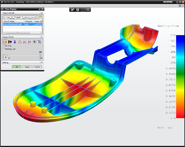
Tools for simulation injection moulding are now available based on technology from Moldex3D
Many users (of all systems) will be familiar with how when editing a part in the context of an assembly, the other parts turn transparent and greyed out. That same effect has now been applied to the partmodelling environment.
When working on a feature, other geometry greys out slightly, so users can see exactly what’s being done and the impact of changes. It removes some of the ambiguity, particularly when working on highly complex assemblies or parts.
The context sensitive menus have also been enhanced. Siemens NX has featured right clicks and radial menus for some time, but with this release, it’s now possible to fully customise them down to the feature level.
Users can access a list of most commonly used commands when selecting edges, faces, features etc.
Moving onto sketching, it’s been expanded to provide users more feedback, specifically in the area of how geometry constraints are displayed as you assign them.
As with most systems, the sketching environment allows the user to dial in lengths and angles shapes are drawn, but it now also shows any constraints that are inferred or defined on the fly.
Some time ago the commands were broken up into blocks so that they can be split out. Now users have a global control over showing less and more as well as favourites to switch off more the advanced options.
This can also be set per dialog if there’s always a preference for the advanced options.
Siemens NX – Synchronous Tech
Synchronous Technology has been the big news around the Siemens PLM camp since its release into NX 6 a few years ago.
As ever, the Siemens NX implementation differs in that it’s much more cohesive and more integrated into the standard set of tools that in other Siemens products.
The simple fact is that the workflow fits better because NX users are more used to working with complex geometry and a different set of tools.
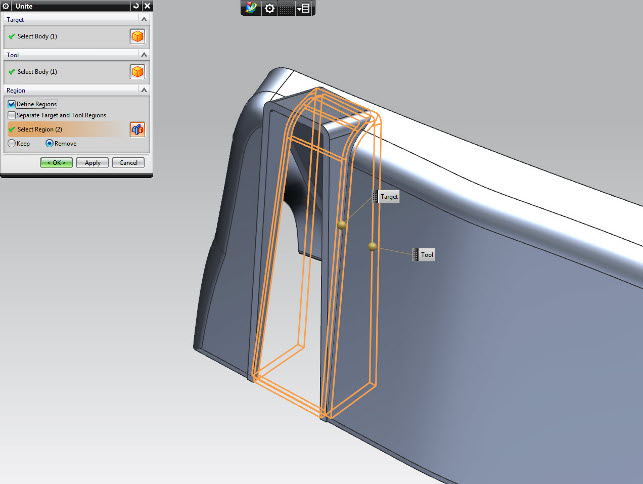
The new ‘unite with regions’ command allows the creation of complex intersections of geometry
Over the last few releases, there has been a lot of concentration on expanding out the workflows and use cases. Direct modelling, in whatever flavour from whatever vendor, is a tricky beast.
If geometry is clean and simple, then there’ll be no problems. Face manipulation and feature editing will work like a charm. Problems arise, however, when geometry is less than ideal or there are highly complex geometry conditions.
For example, with multiple intersecting features, particularly fillets, the problems are exacerbated greatly.
The Siemens NX team has been working on the latter in particular, to bring on stream a set of tools that allow the user to dive in and work with the geometry to get the required results.
A good solid example of this is the new Delete Partial Blend command. Directly adapting fillets or complex intersections (think three fillets with different radii running into a corner) by grabbing a radius and trying to edit, traditionally throws the system into a panic. It simply wasn’t possible to edit them all at once.
The new command allows the user to delete segments of a fillet piece by piece. This re-trims back the geometry around it, allows the user to work backwards, remove the geometry and reconstruct the radii as needs be.
Another example is the new capping options when deleting blends. The system can remove the fillet form, but then cap the geometry to a specified face or workplane.
Again, this is a perfect example of something that can now be done in a single operation. It could be done before, but in a couple of steps, adding more weight to the feature tree.
Feature flexibility
The integration of sync tech has made for some great updates in some very specific feature sets.
Again, this is a good example of how the ability to make design changes, add features and have the system automatically handle the ordering of features in the construction history to get the intended results and maintain design intent.
Rib creation is one such example. Now, you just create the sketch (or drag in from the Reuse library) and define the parameters, such as direction and draft angles. The system then creates the rib features, extending them to the outer limits of the part automatically (typically, the internal skin of the part). Should it encounter mounting bosses and such, that would typically ‘stop’ the feature extension.
The interesting thing is it will pass through them and out the other side — but not interfere with the existing features.
Another example is the new Emboss body. This allows the creation of a ‘cut out’ feature (think, cut out feature on the exterior of a plastic part) after a part has been shelled and worked on. Using this feature, the system maintains the wall thickness of the part, even though it’s created after the shell.
The final example is a big one. The new ‘unite with regions’ is a complex operation to try and explain in words, but the concept is that this is a super boolean operation.
Imagine taking several bodies (perhaps developed by different team members using Part Modules introduced in the last release), and wanting to combine, trim and delete various sections of the geometry.
In previous releases (and in other systems), multiple operations, multiple trims and such would be needed.
With ‘union trim’, this can be done in one operation. That makes the creation process easier, gives users a more streamlined construction history and makes edits easier.
There are also a couple of tidy up ‘enhancements’. The deletion of bodies is now stored as a feature, which makes it traceable (super handy for automation or rules-based design).
Features can now also be automatically coloured by type, giving a clear indication of holes, blends, chamfers and such.
The hole truth
In today’s highly advanced design tools, it seems a little odd to be discussing hole feature creation, but when you get into the details of what NX now has, it’s clear that there’s a great deal of thought gone into the development of this particular enhancement.
Consider the engineering design process in many instances. While the 3D CAD world focuses on the construction of geometry, the engineering process often centres on what’s not there, rather than what is physically present.
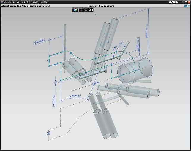
A new workflow allows users to sketch out holes to nail performance and function
Think about pumps, engine design, fuel injection systems. The function of these products centres on the spaces in where no material exists, where gases or fluids move or interact with other actions.
The area around those voids really just supports them, adding mounting brackets and interconnects.
Siemens NX 8.5 allows users to essentially start with a sketch of a part, add in, parameterise and optimise the placement of hole forms (whether straight, countersunk, threaded etc) in solid geometry to validate their position and form.
Then, once you’re happy with things, add in the surrounding geometry. When everything is complete, the user then removes the holes from the model and creates the form of the part.
While I’m sure you could get round this with a few operations and workarounds, the simple fact that you can start with the most critical forms, visualise and adjust them and only then, move them into negative features, could be a great benefit to many.
It can also support a few downstream applications in terms of casting and core preparation.
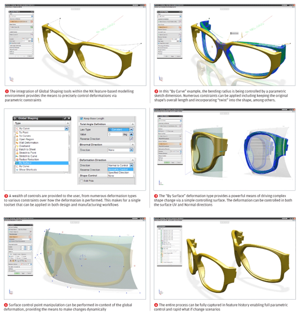
Global shaping
While the tools we’ve discussed so far are iterations of existing tools, this one is a big shiny new one for Siemens NX.
Referred to as global shaping, the concept is to apply global deformations to a set of geometry, rather than tweaking faces and such.
Take a set of geometry (however it is created), then create two reference sets of geometry. The goal is to take the 3D shape, use one reference set as the start point, then morph the geometry by adapting the initial reference to the new one.
One workflow is using curves as the start and end point. The other workflow, which gives more control, is using two sets of reference surfaces.
While the curve workflow is ideal for adding simple shape deformations, the surface method offers more control over specific portions of the process.
Our workflow shows how it works, but you have control over the twist function, to adapt the geometry in 3D space and control over the length of the output geometry, so you can make sure the object doesn’t grow unexpectedly.
While it’s certainly not unique to NX, ‘global shaping’ can be used to make all sorts of changes on a global or localised basis.
It’s worth noting that although localised changes can be made, which is typical of similar tools in other systems (such as Delcam’s PowerShape) in NX the whole body participates in the deformation so unaffected areas that have features like holes and blends will now be b-surface in type (e.g. no longer analytic geometry).
One approach to this, which is common in many other systems as well, is to divide the body into affected and non-affected areas. Perform the deformation on the affected area and then combine the pieces back together.
This would provide a best of both worlds solution to the challenge and in some ways is a better way of handling this on a global basis.
HD-PLM & PMI
To round things out, let’s talk about HD-PLM and Product Manufacturing Information (PMI).
HD-PLM is part of a Siemens initiative to bring greater clarity to the complex and often overwhelming data that’s captured as part of the product development lifecycle — particularly for those heavily engaged in Product Lifecycle Management (PLM) with Teamcenter.
The goal is presentation of that data, linked to the 3D product model, so that users can gain an idea of where issues are, the status of various aspects of the project, and to discover information more easily — so it can be acted upon.
In NX, the tools are built directly into the core of the system. The various areas (check mate, product template studio, requirements validation and issue management) are presented in the form of visual reports, now all from a single dialog.
These allow users to inspect various aspects, look at the report, click the references and have the graphics window show what these issues relate to directly on the model.
For this release, these are better integrated and also bring on stream new checks for PMI. For those unfamiliar with the term, PMI or Product Manufacturing Information is 3D annotation.
The concept is, rather than creating a model, then documenting GD&T on separate drawing sheets, everything is stored on the 3D model (then extracted into drawing sheets if/or needed).
There are now a host of tools built into the system to ensure that PMI data is correctly defined both in terms of semantics and syntax. They try to ensure that there are no typos, formatting errors and a fully comprehensive set of PMI data.
For example, a PMI that refers to Datum E will check that Datum E actually exists in the model and is available. Errors are flagged up in a dialog either as a warning or a violation and clicking on each in turn shows where they are and what’s wrong so it can be fixed and resolved.
While it won’t ‘idiot proof’ the process, it’ll reduce the risk of simply forgetting some of the basics — which we’ve all done.
Siemens NX – Drawings
While it’s good to talk about PMI and 3D annotation, drawings are still the most prevalent way of representing annotation and documentation within engineering.
That said, with the move to a 3D annotation based process, set-up of those drawings will be more optimised. And while Siemens NX has always had a decent set of drawing creation tools, there’s always room for improvement.
NX 7.0 brought a host of new technologies that allowed lightweight views to be created in a much shorter time frame than was previously possible.

Lightweight drawing views can now be annotatied, measured, dimensioned and sectioned
Siemens PLM has experience with the JT format to thank for much of this and it’s now paying dividends.
In 7.0, lightweight views could be used to calculate each view, but the model had to be fully loaded to do anything useful with it. In the NX 8.5 release this changes and it’s now possible to carry out most drawing processes using the lightweight version, including sectioning, detail view creation and dimensioning.
While for those working with smaller datasets, the difference won’t be as noticeable, for those working with the huge datasets now commonplace in many industries (think automotive, aerospace, oil and gas etc), it’ll make them more productive than ever before.
Interestingly, there’s a new switch that controls when these tools are used, in terms of a part count, so users can finetune the switch for individual processes and hardware.
The other major update to NX 8.5’s drawing tools is drawing booklets. As ever, templates are a good way to go when creating standard drawings of many product types (particularly considering the increasing focus on platform-based design processes).
Drawing booklets allow multiple drawing sheets to be added together into a single data file and have the system generate (or update them) in one go.
Select geometry and create a number of drawings from a list of presets and the system adds them all into a booklet so they’re all together and managed.
They’re arranged in a hierarchal format, so it’s clear which drawings refer to which branches of an assembly tree. And because they’re stored in a single file, management and updating becomes less of a headache for complex datasets.
Conclusion
Siemens NX is a mammoth system and always has been. As such, and as is now common in the 3D design tool field, updates are more about optimising existing workflows and process, rather than adding huge swathes of new functionality.
To view an exclusive DEVELOP3D workflow on Global Shaping click here
The NX development team has put some serious thought to making the lives of existing users more efficient. That shows in everything from the greater use of lightweight geometry in drawing creation, through to the new modelling features like the rib creation, union trim and others we’ve discussed.
Each rolls up an overly complex process into something more efficient, cleaner, easier to manage and in many cases, more powerful.
Some show how the introduction of synchronous technology is moving forward, both in upfront terms of things like the delete partial blend, but also in more subtle ways in other feature sets.
Then there’s a hefty amount of brand new functionality. The new global shape modelling tools are excellent. Yes, there’s more work to be done on finite control over what’s affected and what’s not, but it’s a good solid start.
The new functionality integrating better checks on things like PMI show that the team is looking at how tools are used and how to solve common errors and report on them.
Siemens NX is an extremely powerful tool for design, engineering and manufacture. While we’ve barely had the chance to scratch the surface of the system, there’s a point to be made.
Mainstream modelling systems are hugely popular, but some users are finding that they’re hitting the wall in terms of what geometry can be created, manipulated and taken into production.
As a result, some firms are looking at moving systems to raise the bar and take things further, whether that’s in terms of automation of processes, rules-based design, greater team-based working or pure geometry modelling.
For these firms, NX should be on a shortlist. Of that I have no doubt.
Siemens NX – Design for manufacture add-ons
Alongside updates and enhancements to the core tools in NX, the 8.5 release sees the system gain two new options in the area of Design for Manufacture – both based on third-party technology.
The first comes from Geometric Solutions (a component vendor) and is based on DFM Pro.
DFM Pro is a set of design for manufacture checks that looks at part geometry for manufacturability against a set of defined process including prismatic milling, sheet metal fabrication, turning etc.
Integrated into the HD PLM visualisation environment, it’ll flag up any issues it finds directly on the model.
For example, in a sheet metal component the user may want to ensure holes are not too close to the edge of a plate (companies often want more than one material thickness gap between the edge and a hole) or that a turned part doesn’t have internal corner radii that are too small (based on the available tooling and machine capabilities).
All of this can be reported on and integrated into a working process.
The second is the integration of technology from Moldex3D, a Taiwanese outfit that specialises in the simulation of the injection moulding process. There’s two versions available. Those that have the mould tool design products licensed will get the basic version.
It can be used to define gating locations, mould temperature and material and will offer basic simulation of how the part fills.
The full version adds metrics such as weld lines, air pockets and such. It’s interesting to note that every time the system is run, it stores the results set in the part geometry.
Whereas other systems typically dump the existing results and only keep the current one, this provides greater traceability and ease of experimentation.
| Product | NX 8.5 |
|---|---|
| Company name | Siemens PLM Software |
| Price | from £6,150 |