Solid Edge, as I’m sure I’ve said many times over the last 15 years, has been one of the most consistently impressive mainstream modelling systems. It has moved from Intergraph to its current position as the mainstream offering from Siemens PLM.

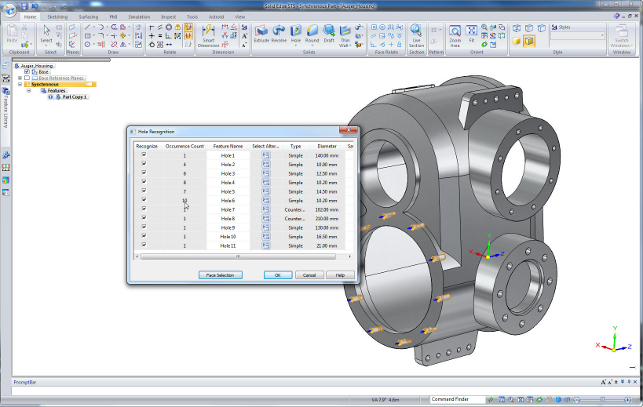
New in Solid Edge ST5 is the ability to recognise holes on imported designs, making them editable features allowing changes to depth or type
Solid Edge covers all the bases in terms of 3D part/assembly modelling and 2D drawing production, but also common simulation tasks due to the integration of the NX Nastran solver directly into the system.
It’s also had product data management for free for quite some time with Solid Edge Insight, which builds a layer that supports CAD data and the complex inter-relationships onto a base of Microsoft’s almost ubiquitous SharePoint. Yet, somewhat puzzlingly, the Solid Edge brand hasn’t been as strong as its potential indicated.

That was until the release of synchronous technology from the Siemens stable five years ago. Although also implemented in Siemens’ higherend system, NX, synchronous technology brought about a tidal wave of direct modelling that enabled users to enjoy the freedom that direct editing of models supports.
Solid Edge’s profile was boosted and the user community as a whole became more aware of this modelling method, which removes the reliance on a linear history of features to construct a model and lets the user work in a much more freeform, drag and drop manner.
Now, four years later, the dust is settling. The initial diametrically opposed history and non-history-based modelling technologies are now starting to appear in all but a few systems. Even the last few Solid Edge releases have seen the ordered (history-based) and synchronous toolsets start to merge.
This means that the user can now have both types of features in a single part – using the tools most appropriate to the job at hand. So what does Solid Edge ST5 have in store?
3D modelling updates
Let’s kick off with multi-body modelling. For those who aren’t familiar with it, here are the basics.
Back in the day, most 3D solid modelling systems only allowed the user to have a single manifold body in a part file – everything had to be connected and contiguous. Then came the ability to hold multiple bodies in a single part.

Multiple disjointed bodies allow the user to build to reference features, then construct the connection between the two. Anyone working in mechanism and structural design will recognise the benefit of that.
This is where Solid Edge has been up till ST5. From this point on, it joins most other systems in providing additional capabilities that make the tools much more usable.
Personally, I find working with multiple bodies in a single part much easier than working across assemblies, particularly when complex geometric references are rife. It just makes life easier at that formative stage.
For instance, this means that an assembly model, such as a STEP file, can now be imported into a single part with each part stored as a separate body rather than an overly complex assembly and part structure.
This enables users to make edits and cross part references more easily. Additionally, bodies can be split and merged, bodies added with an import and others can be used to cut geometry features.
When the time comes, these bodies can then be rationalised into a traditional assembly and part structure, with separate part files and references.
Play the slots
Although, this might seem a small feature update, for those that regularly have to create these types of features, it’s going to be a boon.
Users can now create slots with much greater ease – a centre line is sketched, then the system does the rest according to the user’s requirements.
The benefit is that the centre line is retained and can be used to mate together assembly parts that run in that slot. It’s easy to redefine and edit, but also easier to create more realistic mechanisms.
Making data reuse more intelligent
The ability to work with imported models from disparate systems is an age old problem and something that Siemens seems to have focussed on for this release.
Synchronous technology allows models to be manipulated easily if the data has come from other systems. Building on this, the ST5 release introduces two new tools that allow users to bring geometry in and find and fix problems to make data re-use easier.
The first is the Geometry Inspector. This looks at the imported part and finds geometry problems that can cause errors downstream such as self intersection degenerate geometry and loop inconsistencies. It’ll find them, try to fix them and make the geometry workable.
The second tool is the Geometry Optimiser. This goes beyond the Inspector tool to improve the geometry.
It can redefine the precision (read: tolerance) of the data and can replace blend surfaces where appropriate. It’s interesting to see the geometry wrangling tools built into this release.
While these are now commonplace in many systems, when those systems have a reliance on direct editing, the need for good quality data is paramount. When a system relies on automatically tracking the geometric relationships (using planarity, concentricity, tangency and such) to make edits, the data needs to be in a good state.
Consider fillets. They’re applied with abandon quite often and some systems don’t make the cleanest job of defining them.
When loaded up into a direct modeller, editing them is either a nightmare or simply impossible – particularly once you get beyond either a constant radius applied to a straight edge or more than two fillets at a junction.
Another tool that’s going to assist with data reuse is hole recognition. This will automatically identify all the holes in a single part. It will find simple (straight bore), counter sunk and counter bored holes and make these into intelligent, editable features.
Simulation
The ST2 release saw the introduction of a completely new set of simulation tools – Solid Edge Simulation – built directly into Solid Edge.
Siemens PLM already has a wealth of knowledge in the field of simulation and analysis with the tools built into NX, the NX Nastran solver and, of course, the legendary pre and post processing application, Femap.
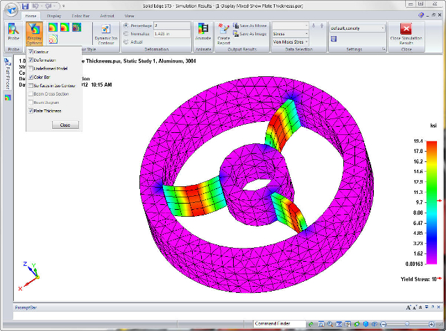
The intervening releases have seen more tools built into the mainstream system that cover not only the basics of structural analysis, but more advanced techniques. A good example is the ability to automatically create web network models where thin walled parts are simulated using mid-plane models to much greater efficiency.
Elsewhere there are new tools to create curved beam elements as well as linear elements, again, for the sake of efficiency. This works in pure beam-based models as well as mixed meshes.
On the subject of beam elements, the system will also now display a face thickness so the model is more representative of the actual part, rather than an idealised model. In terms of what can be modelled, the system also now allows the user to couple steady state heat transfer with structural and buckling analysis.
Drawing and wire harnesses
Solid Edge has always had a well developed set of drawing production tools – it’s even given away as a 2D system in the form of Solid Edge Drafting.
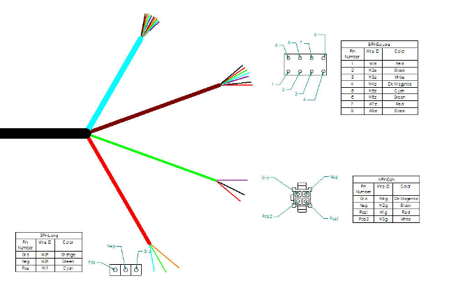
This release sees the introduction of a new area of functionality for those working with complex wiring problems and the creation of nail boards for harness design. All of the tools are there.
The starting point is importing a rat’s nest from the electro mechanical design tool. This has been a part of Solid Edge for some time, but the user now has the ability to flatten a harness into a 2D drawing, and then add the connectors and additional annotations, such as conductor tables.
In terms of general updates, there are a lot of smaller tweaks. The two most interesting: firstly, alternate assembly positions can be shown in a single view; and secondly, the user can create large tables from a drawing view on a separate sheet without having to load the reference geometry – simply point it at the appropriate file.
Conclusion
Solid Edge is moving up in the world. More users have heard of it and know that it offers something perhaps different from its competition.
Ultimately, synchronous technology is a differentiator at the point of sale, but for those adopting the system, it won’t be a major upheaval. The system is progressing nicely to close the gap between the two modelling methods so that it becomes a single toolset.
The updates made in ST5 are good solid improvements. The reworking of the multi-body working methods are ideal and support the way many users want to work, rather than having to work the way the CAD system demands.
The geometry fixing tools are also testament that Siemens is working to provide not only good editing tools, but also supportive tools to help get the geometry in a fit state for editing however the user wants. And when you consider that a large proportion of Solid Edge users are in the sub-contract, supply chain environment, the ability to work more intelligently with third party data is undoubtedly a good thing.
Lastly, the updates made to both the simulation tools and the data management environment are seeing the system and associated applications fleshing out nicely to offer a robust set of tools for design, simulation and data management.
Insight XT:SharePoint – based PDM
Alongside the major 3D modelling and documentation updates, Siemens PLM is launching a brand a new SharePoint App InsightXT.
This is for Solid Edge users who are finding that, as the volume of their data grows, the use of Windows folders and network drives is limiting their ability to complete design projects efficiently.
Siemens was amongst the first to build a data management tool on top of SharePoint way back in the early 2000s.
For those unfamiliar with the concept, Microsoft’s SharePoint is a document sharing and collaboration platform that’s built right into Microsoft Server installations. The original Insight allowed users to access CAD data directly from within Solid Edge and share designs with non-CAD users through SharePoint.
Now, while this is suitable for many, those looking for something that handles the complex nature of the relationships between CAD parts, assemblies and drawings, managing workflow, multi CAD capabilities and more would be looking for something else.
Siemens has the Teamcenter Express offering, but, for some, it might be a little overkill.
Solid Edge Insight XT sits nicely between Insight and Teamcenter Express. This extends what the current Insight offering does by layering tools on top of SharePoint and supporting those complex inter relationships and automation of everyday tasks allowing users to work with linked documents (think PDFs, office docs, spreadsheets etc) as well as Solid Edge data.
Other individual CAD files can be included, such as AutoCAD DWG files, useful if you are migrating from AutoCAD or receive DWG files from suppliers and customers, but if multiCAD capabilities are needed then Teamcenter Express is for you.
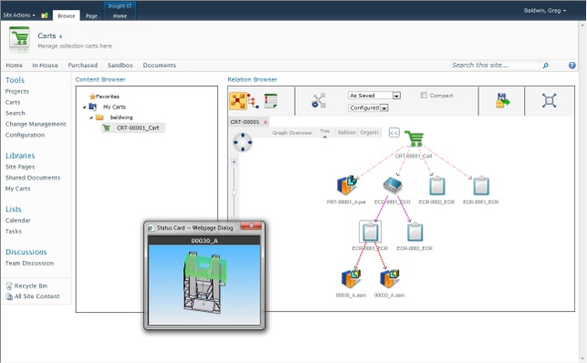
Solid Edge is a very graphical system and Insight XT brings this philosophy to data management, something that designers will like. Some interesting new and very rich data visualisation tools help to get a view on how documents are related, BOM are structured, where parts are used and how design changes will affect other parts.
Insight XT is ideal for Solid Edge users who have many older 2D CAD drawings, need to quickly identify all the documents associated with an Engineering Change, quickly produce accurate BOM reports for manufacturing and need to be able to see the design work that is associated with a specific project and understand the status of the project.
While the base level Insight is a free system, Insight XT is £1,380 and £920 for customers with Solid Edge classic or premium. It’s also worth noting that existing customers wishing to upgrade from Insight should take time to evaluate it first.
| Product | Solid Edge ST |
|---|---|
| Company name | Siemens PLM Software |
| Price | on application |