Optimisation is something that every designer or engineer is familiar with. The process involves stripping a form down to a reasonable structure so that it meets fundamental performance requirements, such as function, mechanical and thermal.

Fig 1. Inspire has a non-standard, yet clear interface that enables exploration
As a purely theoretical exercise it can be done without restriction, but problems arise when using a software system to support the process.
Looking at the most widely available optimisation tools out there (most Finite Element Analysis systems include such tools), they rely on the design of experiments method. In other words, the user takes a model, parameterises it, gives the system a set of inputs, variables and a goal, and has the system iterate it to find the best solution.
When this is compared to the theoretical blue sky approach, it becomes clear that the results from a typical software optimisation process are restricted to the model that is used. Essentially, the user is optimising within a very confined set of options. The old adage “evolution, rather than revolution” holds true.
So, what if the user wants to explore a mechanical design problem with more freedom than that afforded using typical software simulation methods? Enter Altair’s solidThinking Inspire.
Standalone optimisation
solidThinking Inspire has been on the market for a couple of years now. Initially introduced as an add-on to Altair’s solidThinking Evolve 3D modelling application, it’s now being sold as a standalone product.
The concept is that in a single system the user can load in or model up a rough set of geometry, apply performance and boundary conditions (loads, constraints, pressures etc), then use a method of topology optimisation based on Wolff’s law.
For those unfamiliar with Wolff’s law, this is a 19th century medical theory that states that bone, in both humans and animals alike, will adapt to the loads under which it is placed. If the loading on a particular bone increases, the bone will remodel itself over time to become stronger to resist that sort of loading.
When implemented in a software solution, this looks like a simulation process that will solve according to the required loading conditions and find areas where material can be removed from the underlying mesh. While this sounds interesting at the higher level, what’s key is how it’s actually used.
So, let’s walk through the process of setting up a problem with the application.
Defining the design space
As with any simulation task, the process of building up a job begins with defining the boundary conditions and the geometry — both of which are fundamental to obtaining an accurate solution.
The user interface isn’t one that could be considered standard — it has a series of icons across the top of the screen, each with multiple uses and different commands.
For example, while the sketching tools are pretty self explanatory, the Boolean icon contains cuts, intersects and unions, along with all the options, in a single icon.
It’s worth spending a little time reading the documentation and trying to find out how each works. Once familiar with this approach, it will make sense.
Another thing worth noting is that the system is available on both the Windows and Mac OSX platforms, operating exactly the same way in both.
When it comes to defining geometry, there are a number of options.
Inspire allows the user to import geometry from a wide selection of CAD geometry formats and systems, including AutoCAD 3D, Unigraphics, Catia, SolidWorks, Pro/Engineer/Creo, Parasolid, STEP, ACIS, JtOpen, and IGES.
This geometry can be brought into the system and then direct modelling tools used to defeature and adapt them to the simulation process — not only removing fillets, chamfers and small holes, but also making more wholesale edits to existing geometry.
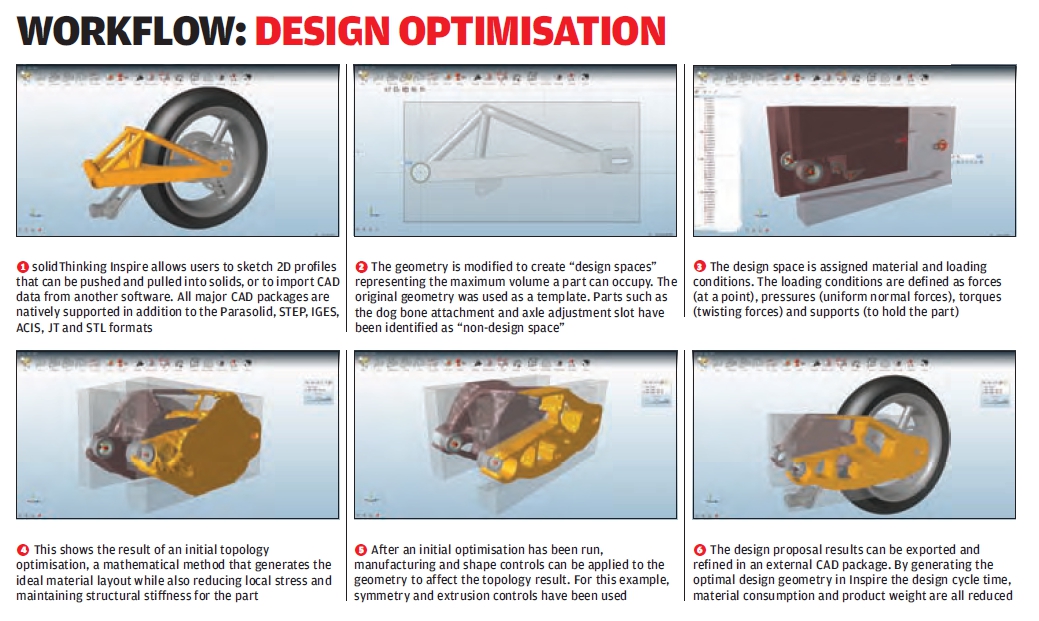
Alongside this, the system also includes a well developed set of sketching and direct modelling tools to help the user work up geometry from scratch. As shown in the workflow below, the user can combine both approaches to bring in an existing part model and use it as reference to create the ‘design space’.
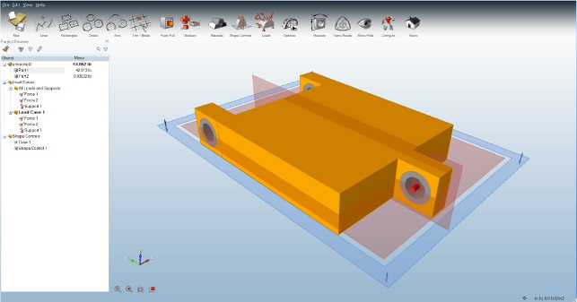
This design space is key to using the system efficiently.
In the latest release, it’s now possible to have two types of geometry in the model. There might be those components that are fixed and are always required, typically mounting components, interface geometry and such.
The design space, however, is where the action takes place. It’s this body of geometry that the system will optimise.
Essentially, the user first defines the geometry for both non-editable features, then the design space in which the system can work. It’s defined with a simple right click to select the design space option.
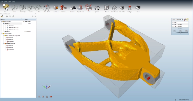
This will change the colour and label it clearly. In figure 2 the design space is in orange, while the non-editable parts are in grey.
Defining boundaries & loads
While the geometry is key, similarly, ensuring that the boundary conditions are proper is also fundamental.
Within Inspire, forces (at a point), pressures (uniform normal forces), torques (twisting forces) and supports (to hold the part) can all be defined by selecting the appropriate faces or other references.
The load can then be defined as well as any other directional information.
It’s worth noting that while the system allows the user to define specific values for forces and such, it’s not key to using it.
The idea is that these values should represent the priority and relationship between the various forces, torques and pressures, rather than absolute values.
In the latest release, a draw direction can also be defined. This will be invaluable for those working with cast or moulded components as it skews the results to ensure that the manufacturability of the part is factored into the process.
The final stage for the design space is to define a material. Again this isn’t essential, but it gives the system guidance as well as minimum thickness values for the optimisation process.
Setting up goals
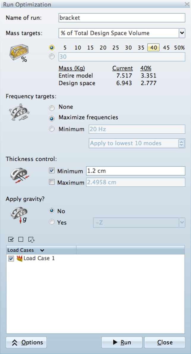
Compared to other simulation tools, the goal setting in Inspire is straightforward.
From a single dialog, there are a number of controls. The key one is the mass target input. This allows the user to define a percentage reduction that they want from the simulation process or a target mass.
The user then has the ability to define frequency response goals whether that’s to maximise them or to find a minimum.
There’s also a thickness control (this defaults to the material settings, but can be overidden) to ensure that the structure doesn’t become too thin.
The last options are to choose whether or not gravity is applied, which is useful for those users working with space applications.
Results
Once the results sets are back, they can be opened up and inspected.

There are tools there to run through the decimation process with a slider (see Figure 3) and inspect all the information that has been provided.
The mesh will be rough but it’s a decimated mesh after all.
The idea is that it will provide the user with inspiration for the proper design.
The geometric lump can be exported as an STL, then used as the basis for proper CAD work.
Conclusion
Simulation is growing in adoption and many are looking at optimisation as a new way to find areas of innovation in their design and engineering work.
While that’s happening, it’s clear that although traditional parametric optimisation offers potential, for those looking for radical changes to existing products or novel ways to solve their engineering issues, something else could be handy.
solidThinking Inspire is a standalone implementation of technology that does exist elsewhere, but if the user already has invested in a simulation system that doesn’t have it, then it’s a solid companion.
Using a system like this could provide insight into potential new design directions that couldn’t be found elsewhere.
Design and engineering is all about thinking differently and sometimes a helping hand can’t hurt.
| Product | solidThinking Inspire |
|---|---|
| Company name | Altair Engineering |
| Price | £5,500 |