We’ve looked at VISI from Vero Software regularly over the years, but the last few years have perhaps seen the biggest change in the this Cheltenham-based company and its products, especially following the acquisition by Hexagon in 2014.
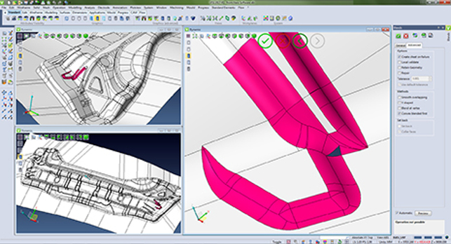
If the blend fails, the system will give you the constituent surfaces, so you have a better chance of building a blend manually
VISI has matured and grown in terms of both depth of functionality and the areas it covers. Its reputation has been built in the complex world of the mould and die market — where the ability to wrangle imported data is on equal pairing with its ability to take those final forms into manufacture at the highest quality. Along the way, the VISI product stack has gained progressive die design tools, injection mould flow simulation and much more.
The 2017 release is the second major annual release (with point updates in between) since the acquisition. And this acquisition certainly bolsters Hexagon’s industrial might adding to the arsenal of knowledge and technology that it already has in its portfolio.
Vero brought not only VISI, but the likes of Edgecam, Alphacam, Radan, Machining Strategist, PEPS, Surfcam and WorkNC; then there’s the tools that Hexagon already owns such as Intergraph, a number of metrology solutions (both hardware and software related) and much more.
We are curious to find out how this will influence the development of the system but to get a feel for where things are at the moment, let’s look at the general updates that apply across the entire suite of VISI’s capability first. We’ll then dive into the specifics relating to both design and manufacturing/machining.
Perhaps one of the biggest updates to VISI relates to licensing as well as how the system handles transition from one release to another.
Licensing has been updated to bring it up to speed with what users expect these days. The management of the various modules, configurations and user profiles are much more flexible and can be administered remotely. For example, a company might purchase five seats of core VISI, but have two floating licences of electrode design or flow analysis. This is much more easily configurable, both in terms of having them available on site as well as, should the need arise, allow them to be checked out and taken off site.
In terms of handling those inevitable software upgrades, again the process has been made more efficient. Firstly, the company has moved from a twelve to a six monthly release schedule, with each year’s release getting an R1 and R2 update. To make the updating to these releases easier, the company has also worked on making the transition more straightforward.
The migration tools now do a much better job of handling any customisation or configuration you’ve done on each seat and brings these across with each update.
Whereas previously you would have had to reconfigure your system in terms of not just toolbars, command structure etc. but also how your users handle things like datums, clearances and all that manufacturing best practice. It’s now brought across with each update, meaning downtime is greatly reduced.
VISI 2017 for design
VISI’s power has always been focussed on the mould and die market — its speciality has been the handling of complex 3D part data and large data-set assemblies, whether that be injection moulding tools, or progressive/stamping dies. That said, customers have asked for more tools for 2D sketching of geometry, which have been incrementally worked on in recent releases.
For 2017, there’s a lot more feedback at the cursor or on the model, rather than dialogs, combined with more dynamic snapping tools for dimensions, angles and other references (such as end and mid-points). These allow you to sketch out your geometry quickly, then dial in the precise dimensions to finalise its form.
Following on from this, editing that same 2D geometry is also more efficient. With a quick double click on an entity, it’ll give you end-point handles, angular rotation and more, all working dynamically to let you snap your geometry into place, rather than constantly referencing separate dialog boxes.
Elsewhere, there has also been work done on the selection methods that include new tools to allow you to grab the geometry you want, whether that’s with a dragged window, a pick or the new brush selection. When combined with the new ‘heads-up’ display controls (at the top left of the modelling window) and a move away from reliance on dialogs, the whole system feels snappier and more intuitive all-round.
Even when you do need to refer to a dialog, these have been worked on to either reduce on-screen clutter or to consolidate separate commands into a single operation. For example, surface extension, a common operation in tooling related design, previously had multiple options and commands. These are now all integrated into a single set of options, so there’s no searching around for the exact method you’re looking for — it’s all there to see and work with.
Modelling for design
Now for the modelling-specific updates. The first area relates to blends, which is notoriously difficult to create in most circumstances, but when thrown into the requirements of the tooling design industry can become a complex task.
What’s interesting about the successful creation of blends is the requirement to have construction geometry that supports the trimming and blending operation.
If your surface ‘sheets’ don’t extend properly, then the chances are that you’ll end up with a failed feature.
If you’re constructing geometry from scratch, this is pretty easy to handle — build the surfaces so they overlap or intersect, then the feature will build.
In the tooling environment, you’re typically not going to have access to that native constructional data to begin with (especially if you’re working with the likes of STEP data). In which case, you need to recreate ‘untrimmed’ surfaces to use as the basis for blending operations.
To get around this, VISI now has additional options to “Create Sheet on Failure”. If the blend fails, the system will provide the constituent surfaces, so you can create those extensions and have a better chance of building a blend manually.
Another operation that’s intended to let you create complex forms where previously they might have failed, leaving you in the lurch, is the Cut Body Command. This allows you to sketch geometry (either in 2D or picking 3D geometry references) to use as the reference for splitting a body.
In the past, these would have required a joined and fully intersecting set of 2D slicing geometry to work it (along with a direction). Now, you can select different edges or sketches to create a split, and these can be unconnected. As long as they intersect in the direction of a cut it’ll work so there is no need for projection (they don’t even have to be in the same plane).
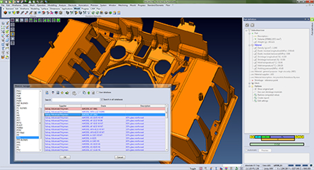
The integrated material library contains the shrinkage information relating to the polymer you’re working with
Differential shrinkage
Let’s now look at some of the mould design specific tools. The previous Differential Shrinkage operation has been removed, but has been added back into the Part Definition dialog — with a lot more capability.
You can take advantage of an integrated material library, so when you define your part, you choose the material which contains the shrinkage information relating to the polymer you’re working with. You give it a geometry reference that defines where to work from with regards to non-uniform shrinkage (typically, a gating location) and the system adapts the model to suit and account for predicted shrinkage.
Although all of this was there before, the difference now is that the end result is a meshed part used throughout the moulding analysis. The system automatically runs a thickness analysis to show how wall thickness varies across the part, and even presents an estimated filling time (with single or multiple gates).
Additionally, because you know the geometry and material, it’ll perceive the mould temperature, filling time, holding times and cooling times. It will then provide a process report, allowing you to experiment with gate locations.
The report presents three categories of part quality: coarse — where the part may not be dimensionally critical; technical — where the part maybe aesthetically critical; and precision — where the component may be part of an assembly or fixed to other parts where feature accuracy is fundamental. This type of quick view analysis is ideal for those involved in quoting or part-time flow analysis.
Cooling circuit validation
Shrinkage analysis leads onto the next step, which is cooling validation. After all, you now have a great deal of information about the injection process but what you need to find out is how efficient the cooling process is.
This starts with resultant mesh from the previous stage and you begin to quickly sketch out your cooling paths — this can range from simple sketch entities, through to a solid, fully formed model. These don’t need to be massively complex or be anywhere near finished.
The system does all of the donkey work, finding the path from your entry to your exit point. If it’s a complex cooling network, it’ll ask for additional information (such as plug locations and flow rate) if it’s not present already. Once done, run the simulation and you’ll get back information to help with finalising your cooling strategy.
The result is a shaded model that shows you material temperature, material fraction (solidity) and temperature of the mould (where more cooling may be required). You can section the whole thing and inspect the results to see inside the part, varying the display settings to discover and explore any issues.
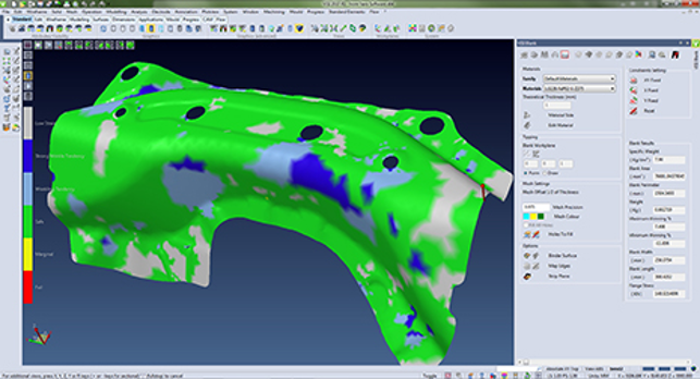
A graphical colour map will highlight areas of failure or areas that are safe during stamping
Forming simulation
A little while ago, Hexagon acquired Forming Technologies Inc (or FTI) which built its reputation on providing simulation of stamping processes and forming tools, including FastForm and FastBlank. These were typically integrated into or alongside other design systems — one of which was VISI.
Since the acquisition, there’s been a move to integrate some of this extended technology directly into VISI to assist with generating flattened blanks from complex dies. While this began with the last release, the end result would have been a flattened part from a 3D model with some analysis of factors such as wrinkle, tear and such.
For the 2017 release, there are additional tools that provide feedback about springback. The result is a mesh-based model that shows the real effect of springback — allowing you to account for this phenomenon during design.
While it’ll only work with single stage forming (multi-stage forming is reserved with the standalone products), you’ll get good indicative information out of it and it’s done right inside VISI. It’s also worth bearing in mind that VISI has, for quite some time, included tools that allow you to work this type of information into your models, so you’ve now got a good set of simulation-based inputs based on industry proven technology.
Interestingly, these tools also lead us onto the subject of safety zone simulation. This is a colour map that will highlight areas of failure, areas that are safe during stamping (with low probability of splits and wrinkles), all done with a colour key.
This isn’t a stamping specific tool, it can be just as useful in the field of progressive die design.
Progressive die design
If the tooling design industry is one driven by black arts and specialist knowledge, then the sub-category of progressive die design is another level of specialism entirely.
Progressive dies are, if you’ve not come across them before, the process used to make high volume and typically smaller scale sheet metal parts.
By running (or progressing) a strip of material through a die, each ‘stage’ of that die will add another feature to the form until you end up with the final part. Whereas larger, perhaps lower volume parts are manufactured with CNC (or indeed, manual) press breaks with each part being worked on individually, progressive dies roll up all of the individual operations into a single form.
Each strike of the die forms a series of operations so, as the sheet moves along, the next operation is applied and at the end, out pops the final part.
This is why the use of stamping simulation is growing — to accelerate that learning process, without having to burn through millions of dollars’ worth of tool-steel.
Because of the nature of the beast, progressive dies are a mix of folding and unfolding forms. Then add to that the developing dies that create those forms — and it’s inherently complex.
VISI has supported progressive die design for many years and the tools have reached a level of maturity. That said, there’s still room for adding more intelligence and capability.
For 2017 this focusses on strip studies. Previously, these gave the user feedback regarding the whole process (stress, force required for whole strip and such) in a global holistic manner.
Now the user can drill down a little bit more, diving into each step and inspecting it in a more granular manner discovering information about bending, shearing and flange stress as well as lifting stress on a step-by-step basis. This can then be factored into the design process and your machine parameters adjusted (it even allows you to factor in more aged machinery with a safety value).
In conclusion
For me, the 2017 release shows how the Vero team is both listening to the manufacturing market and looking to where it can take advantage of technology elsewhere within the Hexagon group.
As highlighted at the start of this review, Vero’s parent company Hexagon has built a huge mass of technology relating to manufacture — not just mould and die related capabilities but all across the spectrum of manufacturing.
In some instances, this sees technology from more production oriented systems, such as Edgecam, transfer into VISI — as shown with the introduction of Waveform operations into not just the 3D roughing operations, but back down the complexity level, into 2D operations.
Then there are instances of a clear industry requirement or market gap and the provision of tools to solve it intelligently. A perfect example of this is within the stamping design workflow.
There’s a wealth of tech available both within VISI and within the wider Hexagon group to assist. What’s driving this?
The simple answer is that the manufacturing industry is in a learning period. Consider the stamping of steel material. This has been done in one form or another for centuries, meaning that there’s literally centuries worth of prior knowledge and best practice that can be enhanced on and supplemented with technology solutions.
If we take the automotive industry as an example, a die will be built then iterated to account for factors such as spring-back and to dial in the process. An automotive company might typically build three to four of those dies before they’ve nailed it for production. All at a cost that can often run into hundreds of thousands of dollars per die, not to mention the time and effort it takes to manufacture them.
Now consider the shift towards stamping with high-strength aluminium, in not just the automotive and aerospace industries, but many other sectors too.
If we take the automotive industry example further, the simple fact that a new process is being used means that the number of iterations goes up from three or four to potentially 10 or 12, at the same costs per die set. Why is that the case?
The reason is that the prior knowledge and experience simply does not exist. This is why the wider-spread use of stamping simulation is growing — to accelerate that learning process.
Essentially, it’s providing a means to get up to speed with new manufacturing processes without having to wait to build up decades of experience and best practice.
This is just one example of how, under Hexagon’s ownership, the VISI and Vero brands are growing and the solutions with them. It’s looking for opportunities to take what’s already a mature and robust system and bring new technologies and industry support to the market.
visicadcam.com
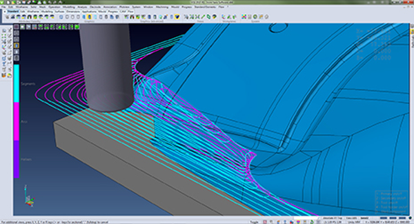
Waveform allows you to combine deep cuts with small stepovers at a higher feed rate to rip out that material faster than would traditionally be possible
VISI 2017 for manufacturing: Twizzle and Waveform
While we’ve focussed on the design for manufacturing related updates in this review, the 2017 release also sees work done on machining related capabilities.
The major updates focus on these three core areas below.
Work piece management: The first is geometry management. VISI has always done a good job of enabling management of the various component parts relating to a project. Consider a full mould stack.
Not only is there the part from which the core/cavities are generated — the mould form themselves — you’ve then got all of the bolster sets, electrodes and cooling channels to deal with.
VISI now allows you keep these together and control them, whether it’s a set of geometry, STLs (perhaps for stock models) or purely sets of faces. There’s no need to preselect these geometry items, you add them from the work piece management list or, indeed, on the fly.
For the times when you have a mixture of prismatic geometry and parts with curvature or small features, you also have control over tolerances for each individual piece of geometry.
2D machining operations: The next focal point is in the area of 2D machining. Whereas VISI has built its reputation on complex 3-axis upwards machining, there’s huge benefit in being able to take care of the simpler jobs in the same system.
The 2017 release introduces a set of pocketing and profiling routines from elsewhere in the Vero group (remember, that includes the likes of Edgecam), replacing some of the legacy code and bringing them up to date.
There’s better corner management, improved collision detection and better optimisation of points. There’s also been speed improvements and better obstacle management (the cutter will pass over them, rather than avoid them completely) — both of which link back to the work piece management — as you’ll have already defined the stock, jigs and fixtures.
Finally, there are new tools for breaking corners and chamfers in 2D operations, so that the cutter will run around a corner to maintain a sharp form — it’s called Twizzle. A useful feature with an even better name.
Vero Waveform in 2D & 3D: Vero’s Waveform technology, for full cutter length roughing of parts with a more intelligent toolpath, has now been built into the 2D operations and the existing beta tested capabilities in 3D have officially started shipping to customers with this release.
As a basic explanation, Waveform allows you to combine deep cuts with small stepovers at a higher feed rate to rip out that material faster than would traditionally be possible. The toolpath is automatically adjusted to compensate for load fluctuations.
Tool engagement is decreased in concave areas and stepover adjusted between passes to maintain the desired engagement. In convex areas, the opposite happens — as the material falls away the toolpath stepover is increased to maintain the too engagement.
Most CAM vendors have been working on similar technology and while each have their own intricacies, this is the basics.
Waveform has been in early access test for the last release, but it finally gets its first commercial production release with 2017. As you might expect, the concentration is in the 3D area.
Combined with high-speed machining techniques (such as managed speeds/feeds/spindle load, smoother ramp in/outs), it can truly strip not only material out of your parts, but also time out of your operations — getting you to final part and shipping faster, which is always a good thing.
What’s also interesting is that the benefits of Waveform are starting to make their way into the less complex, but no less important, 2D operations as well.
| Product | VISI 2017 |
|---|---|
| Company name | Vero Software |
| Price | on application |