
While Vero has a wealth of design and development tools, perhaps one of the areas the company is best known for is machining and support for some of the most complex production methods. Let’s deal with machining and tool-path generation first – because it’s probably the most widely applicable.
As it stands, the system has a very mature set of machining functionality, ranging from standard production 2.5-axis milling and drilling, through 3- and 5-axis machining and now into the realms of more complex machine tool support.

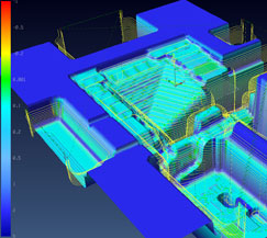
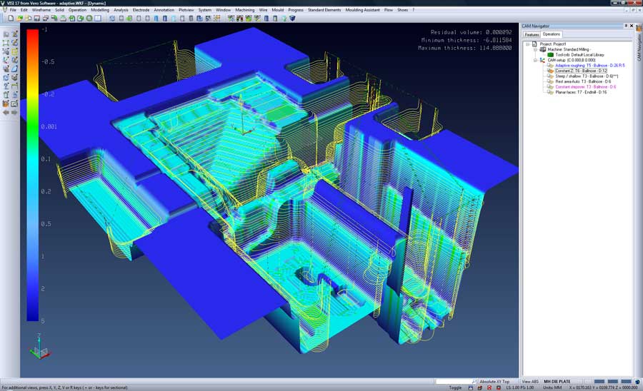
Interactive stock model displaying residual material
Starting with production machining, the new high-speed pocketing feature can be used to create prismatic type features using high-speed machining techniques. This means speedier cutting and also includes helpful additions that adapt the tool-path to finish the bottoms of pockets with a single pass, removing the need to add an additional step.
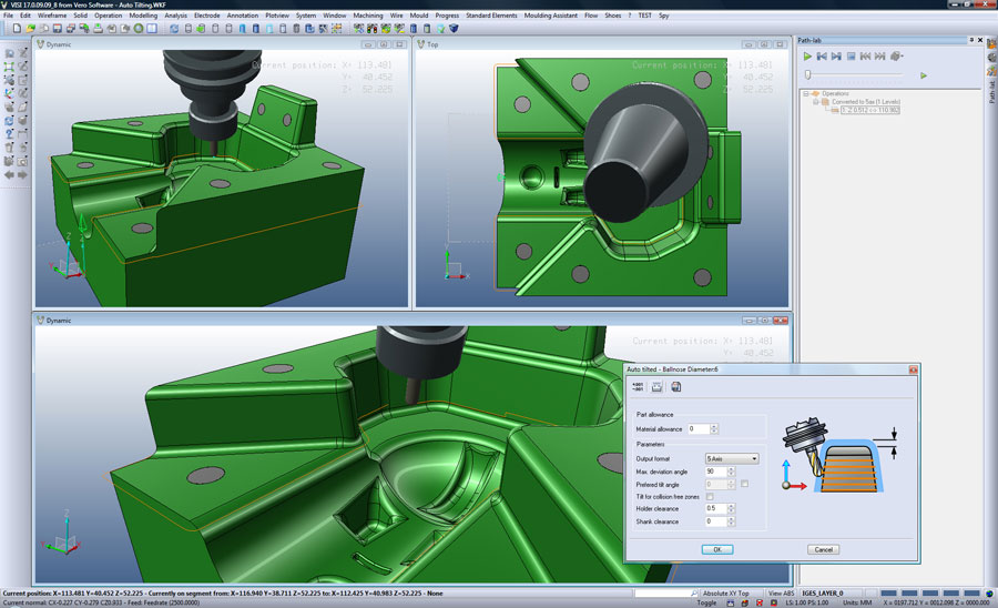
Moving onto more complex machining, this release sees the introduction of a new auto-tilt function, which will help those who are new to the world of 5-axis machining. It allows users to take a standard 3-axis tool-path and convert it for use as a 5 axis tool-path, rather than having to rework it from scratch. This is particularly useful for dealing with both short reach cutters and deep pockets.
VISI has always had the ability to carry out this conversion, but the system presented the user with a bewildering array of options, variables and parameters. The new tool strips out all but the key options in a clean, simple dialog, whilst retaining enough control to fine tune the operations. It’s a fantastic step up into the world of 5-axis machining and puts the technology into the hands of people who’ve never used it before whilst keeping cutting efficiency at a maximum. This is something many machinists will be facing as the costs of multi axis machine tools have lowered and older machinery gets replaced. It even links to the original 3-axis tool-path data, so users can edit it and automatically have the auto-tilt operations applied.
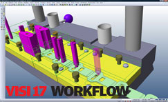
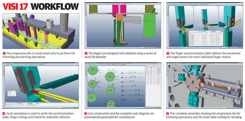
Click the image for an exclusive look at the VISI 17 workflow
There’s also been work done on how the system uses stock models. Firstly, users can now define a stock model as either a bounding box from an extruded profile sketch or from offset from geometry, which is ideal for castings. Then, once in process, as with most CAM systems, VISI uses an incremental stock model that’s maintained with each operation to ensure material is being cut, rather than fresh air.
With VISI 17, the interactive stock model can be inspected and interrogated helping the operator find where excess material remains for each operation. Additionally, there’s a new automatic boundary creation tool which can find areas of specific stock depth. The results can then be used to limit where subsequent machining operations are restricted to.
Other key machining updates include the added ability to generate passes and links separately. While users would typically want to have both created at the same time, these tasks can now be separated, enabling the toolpath to be fine-tuned. For example, removing specific passes, before linking them together to achieve optimal cutter movement.
The final major update for this release is that the feature recognition technology (referred to as Compass) can now be applied to surfaces as well as solid models. While this might sound counter-intuitive, when machining from the basis of surfaces, standard features are commonly found within the same part file (such as complex holes), so the reduced programming time allows users to concentrate on the difficult bits.
VISI Mould
Alongside machining, VISI has built its reputation on mould design tools which are again, a highly mature set of tools. But that’s not to say there’s no room to make things a little more efficient, or in this case, flexible.
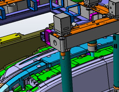
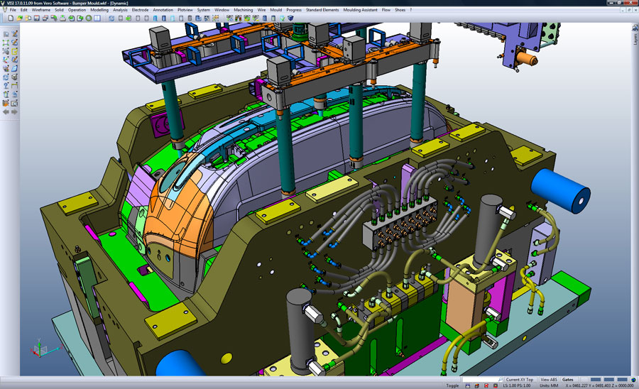
3D bumper mould and hot runner designed using VISI
Catalogue-based mould design tools are excellent for stepping users through the process of building up a mould stack of standard components – but what happens when working on something out of the ordinary, something that requires custom plates, for example? VISI now includes the ability to build fully custom mould stacks, featuring either custom plates, hardware or integrating standard parts (such as pillars, ejectors, bushings etc) where needed. Of course, this might form a new series of mould tools, so users have the ability to save work out as a template which can then be reused on subsequent projects.
The other big news for mould design is the integration of the Cadenas library into the system, which provides access to a huge range of additional catalogues and engineering information.
VISI Progress
Progressive die design is another key differentiator for VISI and an area that is incredibly complex. Because of the way a blank progresses through the punch set, each stage needs to be defined individually. Within a software environment, users define the process in reverse, beginning with the 3D part and unfolding it to achieve a flat blank.
VISI has the ability to take highly complex forms and create a flattened part in one operation, but this release extends these tools to do the same in a step-by-step manner. Using a binder surface, users are able to define the punch form on which to base the unfolding process (this gives the system a fighting chance to work out highly complex geometry transformations).
If a part fails with the automated approach there are new tools to carry out the process manually. Starting with a ‘backbone’ (typically from a section), a series of additional sections can be generated and these can be used to build the sequential steps manually.
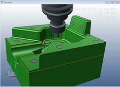
Auto-tilting puts 5-axis technology within reach of people who have never used it before
Once a set of gradually unfolded models has been built, in order to achieve the part development, this data is then used as the basis on which to build the strip layout and of course, the punches required to generate that form. Alongside the die tool updates, there’s also a new thickness analysis tool. This will graphically show critical areas where material is thinning out as the strip moves through the process, allowing users to identify potential areas of tear (where material is too thin) or wrinkling (where it’s too thick).
One of the most interesting things about VISI is how there are highly specialised design and manufacturing tools. A perfect example is the new analysis tool for cylindrical drawing. To create the part, users only need to define the cross section, rotation axis, part thickness and finally select a material from the supplied database. The system then creates the stages required to create that form, including any suspension forms or collars. Because the system has materials knowledge and the required information, users are working with real production data, rather than guess work, to achieve the correct stages forms for the strip layout. This can then, of course, be fed into the tool design.
Another good example is the new support for multi-slide tooling, where there are multiple slides, driving multiple punches at the same time. Obviously these need to work in a synchronised manner otherwise there would be a lot of banging and crashing. It’s an incredibly complex and detailed process and something that can truly benefit from the introduction of some clever technology – which Vero has done.
Starting from the unfolding steps, every finger can be designed by using a series of quick 2D sketches. These sketches are used to obtain the number of movements, stroke value and the orientation of each finger. This information is then used as input data to compile a “computation table” where each action and its associated stroke needs to be timed perfectly to cut out any slack in the operation and to achieve the shortest cycle time possible. The final result is the complete cycle diagram and the construction of each relevant cam as either a 2D profile or a 3D solid.
Conclusion
Taking into account last month’s coverage and this month’s manufacturing focussed content, VISI offers a quite bewildering array of technologies that covers a vast range of processes and tasks. These include the excellent 3D modelling tools that allow users to work with geometry either from scratch or with less than ideal imported data, mould and die design and into the realm of machining and toolpath generation.
Anyone that takes even the most cursory glance at what Vero has to offer for both design and manufacture should see that there’s huge potential to squeeze new levels of productivity from many areas of your organisation.
Next month we’ll finish off our review of the VISI range of products, with a look at VISI Flow, which covers plastic flow analysis for injection mould design.
| Product | VISI Series 17 |
|---|---|
| Company name | Vero Software |
| Price | On application |


