
With its roots at Italian manufacturer Olivetti in the 1980s, Vero Software and its flagship product range, VISI, has a background steeped in the business end of manufacturing. Having grown from a mould and die focussed modelling and machining solution, the range now offers a wealth of CAD tools for simulation, design and manufacturing, even delving into the more esoteric realms of wire EDM.

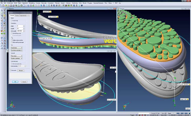
Interactive bending of a solid model using the deformation tools
The last few releases have seen a huge amount of work done on both the integration and extension of the new tools the company has acquired such as the mould filling simulation tools from Plastic & Computers and wire EDM tools from Camtek. So, with this amount of product to look at, we’d better crack on and start with the basics.
Vero has been working hard on the system’s user interface. It looks fresh and modern with a crisp graphics display and a neatly task oriented user experience that helps to instil a certain level of confidence in the working environment.
Specifically, this release features a consolidation of the file/open and file import commands, which were previously separate. Now the user has drag & drop access to all of the following formats – Acis, Catia V4 & V5, DXF/DWG, Iges, Parasolid, Pro Engineer, Solid Edge, Solid Works, Step, STL, Unigraphics and VDA. While this may seem an extensive list, work has been done on the output of data. So, as well as supporting interaction with mesh data, VISI will also read PLY polygon files and will output directly to Z Corporation’s own ZPR format for 3D printing.

VISI 18 also brings on board tools for working with mesh data, which may for instance come from a reverse engineering process or a simulation. All of the tools needed to clean up that data are provided, such as hole filling, rationalising normals, deleting areas of data and sharpening up edges (something that reverse engineering capturing devices suck at). Although it’s not a specialised tool like those developed by Geomagic and CopyCAD, it will let you work with the data once it’s been processed.
In terms of interaction with geometry, the reliance on the dialog has been removed and instead the drag handle approach, now common in all 3D design tools, is used. It’s been nicely implemented here, particularly when dealing with fillets that have multiple radii and other complex areas. The drag/drop and push/pull concept is pervasive throughout the user interface making geometry wrangling much more efficient.
Geometry Manipulation
Whilst many may think that the 3D geometry issue has been solved, it’s clear that there’s still more work to do and VISI 18 shows this perfectly. This is evident in the new Advanced Modelling set of tools, which have been implemented in two forms. The first is the ability to deform a surface model with much more freedom compared to most surface modelling tools.
The user can Stretch, Bend, Twist and apply a Radial Bend (Bend + Twist) to the geometry. What’s interesting is that these tools aren’t restricted to surface geometry, but can be applied to any mix of surface, solid, mesh or indeed, wireframe. In practice, they’re pretty easy to use.
Take the Bend operation for instance and point to two points. The first is where the geometry is held, the second is where you apply the bend. In terms of control, you have a great deal, not only over the amount of movement, but exactly where it’s applied. What’s interesting is how the system applies the changes. It’s capable of maintaining surface quality and you can specify whether the holding condition is positional, tangential or curvature constrained, up to G4 standards (3D acceleration). Similarly, if you Stretch and Twist, all three will maintain the surface quality needed while allowing you to achieve the deformation required.
Target Driven Deformation
The second and more advanced of these tools is Target Driven Deformation (TDD). While the first four operations discussed above allow you to define global deformations, these give a further level of control. Not only in terms of how the geometry is deformed, but also what faces and features are affected and which are retained. In short, they allow you to deform a model based on multiple start and end conditions.

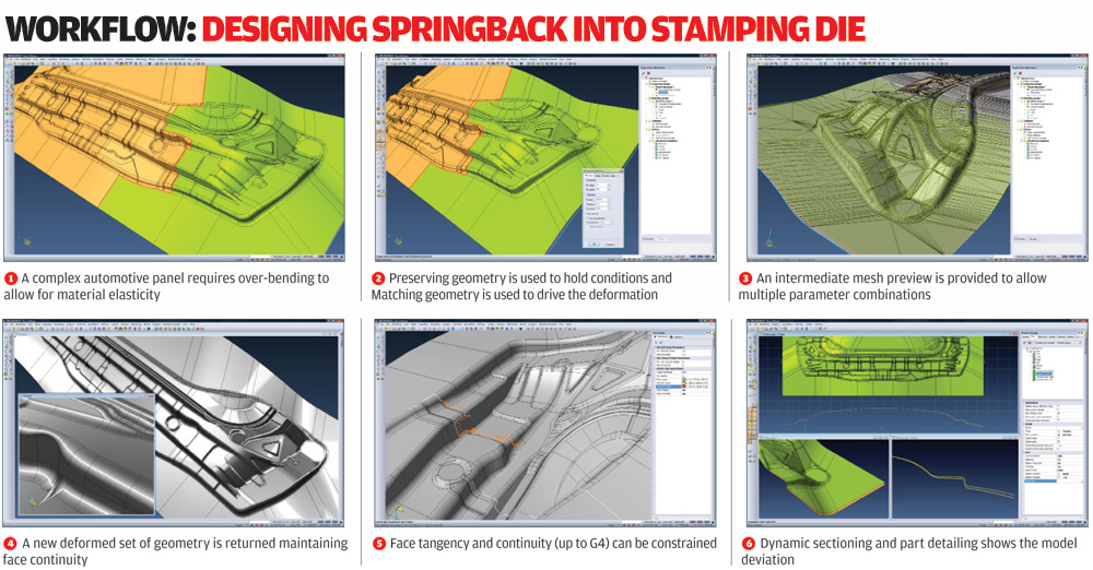
So, think of taking an edge set from a starting model, creating the edge set that you want the model to conform to and having the system carry out the modification. While this probably sounds mildly baffling in text, our 6 step workflow below should show you how it works more clearly.
In order to understand the level of control at hand you need to consider why Vero has provided this tool. VISI is commonly used in the stamping die industry where, as anyone experienced in the field will know, spring-back is a constant problem.
The nature of the process together with the materials used mean that if the die is designed based on the nominal CAD data, the resulting part won’t match. The reason being that while huge force has been applied, the sheet material still retains its elastic nature and springs back out of the die to a different shape. This is a true black art and requires some serious knowledge on a part by part, machine by machine basis.
The way it’s accounted for is by making changes to the die that ‘over compensate’ for the spring-back so that when removed from the die, the part will represent the required form.
The specialist (using digital simulation tools such as Autoform or Dynaform) will be able to look at the part, the production process and predict where the spring back is likely to occur and be able to account for it. The problem traditionally has been that it’s quite difficult to model that design change in order for a die to be machined.
Vero is looking to solve this with Target Driven Deformation by allowing the user to sketch in edge conditions, or take point data from a CMM machine, which defines where the compensation is required, and have the surface matched to those new geometry conditions. Basically, you start with an edge chain, sketch out where you want it and have the system deform the surfaces to effect that change.
Of course, applying this might cause unwanted deformations to specific features like holes and bosses that need to be a specific shape for assembly. For this reason you can use the Preserving Group option to specify areas that are not allowed to change. Chances are, you will use multiple applications of this command to achieve the result you want for complex parts and the system will give feedback about the variance of tolerance (for position, tangency, curvature) and support its use in an iterative manner. It also supports symmetry, if that’s applicable to your parts.
While the example used here is stamping die specific, the good thing is that this type of geometry manipulation can be applied to many other problems that regularly occur, whether that’s fixing small gaps in surfaces, adding draft to a part without affecting key features or to manipulate mesh data. In combination with Vero’s mould filling tools, it’s even possible to discover where a plastic part will warp and define the changes required to overcome that warpage. So the TDD tools will account for it and rerun the mesh file to compensate the warpage.
Conclusion
VISI is one of those very rare suites of products that actually does offer complete design to manufacture capability. Many of the more mainstream vendors, particularly Autodesk at the moment, are making huge noises about how they support a complete process, but the fact is that, until you’ve got the CAM tools in there, you’re nowhere near a fully integrated solution.
While only the major design and mould filling simulation tools have been discussed here it should be clear that Vero are achieving a very happy medium by adding new tools and improving existing ones.
The complete integration of VISI Flow is excellent and offers an interesting alternative to Moldflow as you have the flow simulation tools integrated with a system that actually lets you fully account for problems that may arise. Much of that is driven by the new geometry manipulation tools, which are first class.
VISI has allowed you to work directly with dumb geometry for decades now but the difference now is that it’s been what its users have needed to do for decades as well. And this release shows that this work is still important and the new mesh-based modelling tools, combined with the new deformation capabilities, enable you to make the edits you need, where you need to, without worrying about much else.
We’ll conclude things with a look at the manufacturing update next month and a bigger conclusion, so stay tuned.
| Product | Vero VISI 18: Design |
|---|---|
| Company name | Vero Software |
| Price | On application |


