
With roots in mould and die design, having been the first company to license the Parasolid geometric modelling kernel on a PC in the early 1990s, Vero occupies a unique place in the market.

The blending capabilities of VISI are laser targeted on manufacturing
Its product VISI is aimed at those users involved in producing plastic injection moulds, sheet metal stamping dies and other complex products in the manufacturing sector.
Alongside class A surfacing, pure geometry wrangling and manipulation, the system has always had a healthy dose of CAM within its portfolio. This now extends from simple 2D machining and wire EDM right through to complex multi-axis machining, with high-speed machining standard throughout.
Then comes the more specialised tools, such as plastic flow analysis and progressive die design, where VISI is particularly strong. In short, it’s a very capable system for those engaged in design, particularly within the context of manufacturing.
A few years ago the Vero development team began refreshing the user experience. This work continues with VISI 19 but rather than user interface tweaks, the changes are much more fundamental.
Previously, the system was Action/Object driven. Namely, the user selected the operation (say, a fillet), then selected the object to which to apply the edge or face set. This changes from now on working in both an Object/Action and Action/Object mode.
Those new to the system will find it much easier to get up and run with whilst existing users probably won’t notice a huge difference. The benefit is that menus are now context-sensitive and the selection of commands is tailored to the user’s selection. Importantly, the whole thing is fully customisable enabling the user to switch these tools on/off for specific selection sets and work modes.
Another key change is how the user interacts with geometry selections, particularly when building geometry from existing references. The combination of new selection tools (to grab edges, vertices and planes) and a new move/copy triad, means geometry can be built where it’s easiest to grab references, then move it into position.
One other addition is the custom data monthdouble-click, which allows the operator to define which operation will be called when selecting any geometrical entity.
For example, when a CAD user selects a face, they may want to move or add taper to that face. However, when a CAM user selects a face, they may want to create profile features for machining purposes.
A great deal of consideration has been put into how the operator drives the system and the guys at Vero have done a good job of optimising the user experience.
Blending
Yes. Blending. No 3D design tool’s release would be complete without a nod to creating fillets. But in the case of a system like VISI, which is laser targeted on manufacturing, it’s key.
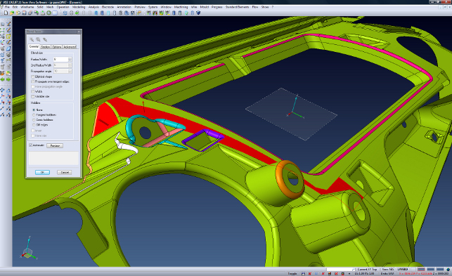
There are a number of new tools worth here. The ‘Blend between Faces’ operation has a great deal of options to get those tricky forms built, with full control over radius and how tangency propagates. This allows the user to tighten or loosen off the geometry, helping to round off those pesky sharp corners.
There’s also full control over hold lines with specific radii. While this is most commonly used in industrial design applications to achieve crisp blended edges, in the manufacturing realm it’s useful for ensuring constant radii rounds in deep and complex pockets.
With a host of tools the user can now work with poor quality data, often the result of imported geometry, as well as the much less common perfect data you see in a demo.
For example, this includes the ability to not trim the original connecting faces of a blend and return only the underlying fillet surface result.
This allows the user to accept the operation, then use the manual tools to trim back surfaces and create the geometry manually, something that isn’t possible in a run-of-the-mill parametric modelling system.
Finally, with the new Full Face blend the user can grab three faces and add a fillet that spans them all, regardless of shape. This is excellent for quickly adding radii during rib design to aid material flow and minimise sticking within the mould.
Interoperability & 3D annotation
There are some interesting new capabilities in VISI 19 with regards to 3D annotation and geometric tolerancing.
While the system doesn’t yet have the fully fledged, ANSI Y14.41 compliant 3D annotation tools, it does provide a toolset that allows the user to very quickly add reference dimensions, assign them to a presentation plane and store them within a model.
Moving onto 3D data exchange, the Vero team has joined the JT partner program and the software now has integrated JT data support at a fundamental level including support for toolpath representation.
For those unaware, JT is a data format that can store both a lightweight tessellated version of a 3D model as well as a more accurate B-rep, which can give surfaces for reuse. It’s typical that many of the systems that support JT can use the tessellated data for reference only, requiring that the B-rep. As Vero can work with both surface and mesh data, it allows the user to export and read both.
Tool Manager
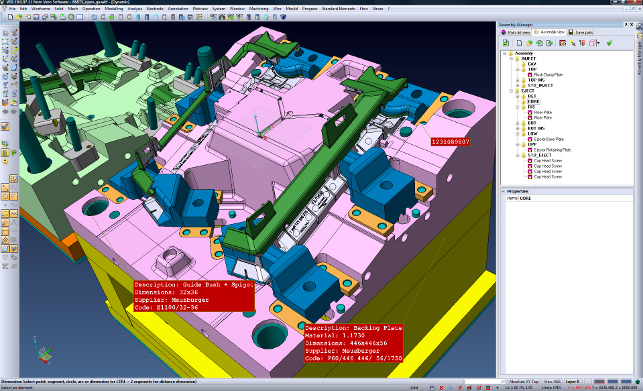
The Tool Manager in VISI 19 is a major development.
Firstly, it manages the hierarchy of the assembly structure and improves collaboration between native and foreign data management as the tree structure can be imported and exported to/from other CAD formats. However, this tool is also intelligently used to manage the tool visualisation.
Within VISI it is possible to have a number of different tree structures that can be switched on/off. For example, it is possible to load a tree of just purchased items or a tree of just the mould bolster set.
This makes it very easy to visualise the assembly in different guises and also create custom exports or custom BOM’s.
Springback modelling
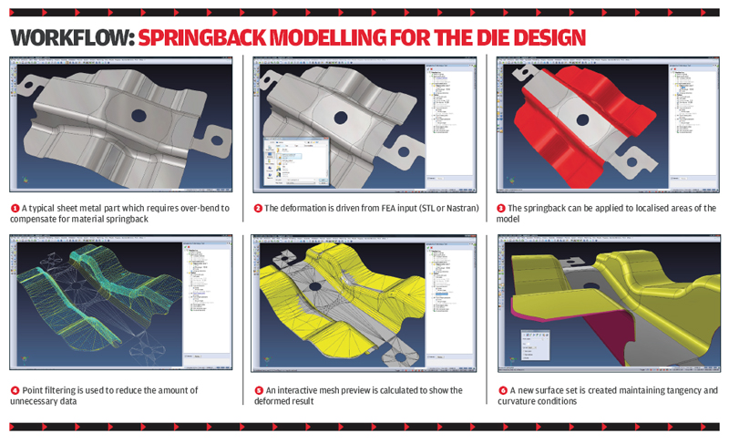
Vero has been building tools to account for spring-back for some time but what has changed with this release is the extension of these tools with some serious automation to accurately define the correct shape to account for material deformation.
Beginning with the standard nomimal shape, there are three options available to define the ‘as manufactured’ shape.
The first uses co-ordinate measuring machines (CMM) to adapt that nominal CAD data using a common set of data points to define how the part has shifted post manufacture. This data is captured using reverse post processors – SurferEVO or VirtualDims. VISI asks for a set of faces to compare.
This allows the user to separate out the faces that are being worked on and then create the compensated result based on the point match and mismatch. It is also possible to adapt the distances to over-compensate. This then pulls the surface into the required position.
The second method allows the user to read data from an Finite Element Analysis (FEA) based system, whether that’s as an STL file or a Nastran deck. As the import options are pretty open, it’ll work with almost every general purpose FEA system as well as more task-specific tools such as PAM/Stamp, FastForm or AutoForm.
When using this method the FEA data is often very heavy so to minimise calculation time, additional skimming tools are available to remove excess clutter.
The final method, by Section, allows a part to be picked, the material properties defined and then a ‘compensation edge’ added. The over-bend angle is then defined by which to pull back the surface.
This adds a number of editable sections along that edge set that enables the data to be rebuilt as required. While it may not have the intelligence of the other methods, it is based on ‘user experience’ and it’s the basis of how this type of repurposing of CAD geometry for manufacturing was conducted before the advent of simulation driven approaches.
VISI flow
Another key area of VISI’s design tools is VISI Flow for plastic flow front simulation and analysis.
Acquired a few years ago, each subsequent release has seen improved integration into the VISI environment. With this release, Vero has introduced VISI Flow Lite as a lower cost of option.
It may not have all the bells and whistles of the full version but with a predefined workflow allows a simulation to be stepped through much quicker.
The enhancements made to capabilities can be split into pre- and post-processing. In terms of pre-processing, in previous releases, the mesh repair tools were discreet and sequential and often had the problem of one repair potentially causing other failures.
To improve the workflow, the user now selects the part, creates the mesh and the mesh checking and repair tools are now all in one ‘Check’ menu.
If only a handful of errors are present, it’s possible to dive in and fix these manually. But the system also has automated tools to fill holes in the mesh and deal with overlapping, overhanging triangles and flipped normals.
The end result of this is a clean, consistent mesh that can be used in the injection simulation process.
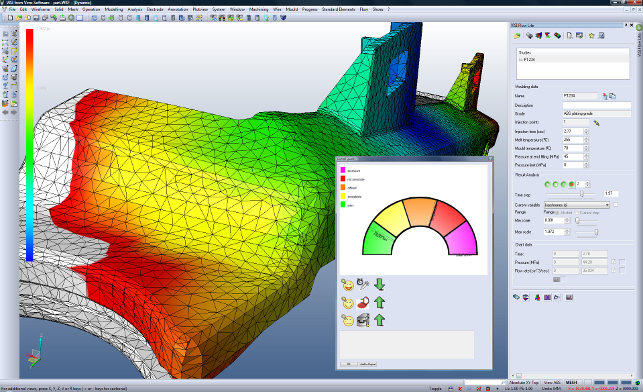
In terms of post processing, the last release saw the introduction of a ‘traffic light’ quality gauge (in terms of fill quality) and this has been enhanced for 19.
It gives feedback about mould temperature, injection speed and melt temperature – all of which can be experimented with to improve part manufacture.
Another post process update is that a part can be rendered transparent to show internal material flow – which is particularly useful when working with highly complex features and bosses.
Alongside this, the sectioning tools can also provide insight into what’s happening within the structure of a part, rather than purely on the exterior. Another key addition is the ability to conduct a holding analysis to show how the part hardens in the mould post injection.
One very useful feature is the ability to overlay the filling simulation on top of the analysis graph and dynamically move a slider along the graph to immediately see the correlation between the filling progression and the graph variables. For example, this could be vital to understanding which part of the filling phase caused a pressure drop.
Final updates for VISI Flow are related to materials (the database supplied has been greatly expanded and is now updated every month with vendor-specific data) and cooling design.
It’s now possible to define the order in which the coolant will flow, all from a single drag-and-drop dialog linking them together. There’s also greater support for different coolant types with the system now supporting water, ethyleme glycol and steam.
Conclusion
It should be clear from this review that Vero is working hard on bringing some rock solid updates and new features to its already impressive product range.
While we’ve covered the design and modelling related updates, there’s similar activity across many of the other areas of the system, which we’ll get into next month.
| Product | VISI 19 |
|---|---|
| Company name | Vero Software |
| Price | Price on application |


