

While Vero’s reputation was built on mould and die design, in 2007 the company acknowledged that there was more to the process than cutting tool-steel and acquired the injection moulding simulation program, TMconcept, from Italian software house, Plastic and Computer.
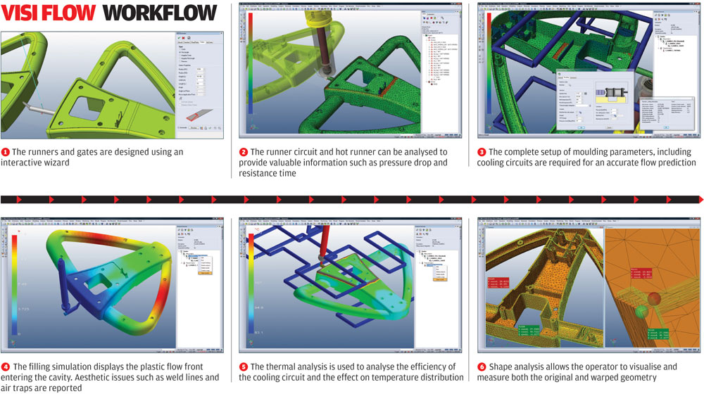
Renaming it VISI Flow, Vero then started work on integrating what was a capable, but user-unfriendly system, into its flagship product suite and it soon became a key part of Vero’s offering to the plastic moulding industry.
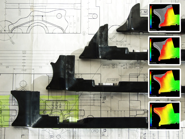
A recent project for BK Tooling highlighting how the actual moulding conditions accurately match the VISI Flow filling results
Now with the technology fully integrated into the core suite, Vero is not only offering its users a more consistent workflow but the additional benefit of having the power of VISI’s modelling tool at hand.
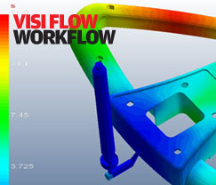
Click here for an exclusive DEVELOP3D Workflow in VISI Flow 17
The most commonly used portion of VISI Flow is filling analysis. VISI Flow doesn’t use the mid-plane modelling methodology often found in other filling analysis systems (which often requires additional geometry preparation) but rather uses patented hexahedral mesh techniques where a mesh-based model of the part geometry is used.
As the system is now integrated into the VISI environment, there’s no data translation required, the user simply switches environments. The first step is to define the parameters of the part, focussing on thickness, material (the system is supplied with a huge material database), gating locations, and the all-important injection parameters such as injection time, melt and mould temperature.
Once the analysis is complete, it’s on to the critical portion of the process – interrogating the results and making informed decisions based on that data.
VISI Flow allows the user to extract all manner of information from the analysis, both text-based (in terms of percentage fill, fill times, cycle time, clamp tonnage and shot size etc) as well as more visual data. The system can be used to create static and animated imagery that displays how the part filling process progresses over time, plus how it cools. Alongside this, it’s here that the user can identify cosmetic issues such as weld lines, air traps and such.
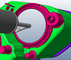
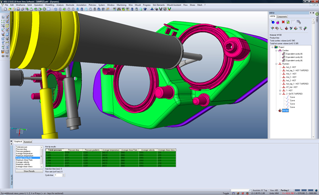
The hot runner (HRFill) application is used to simulate the performance of the hot runner system without the need to simulate the entire mould. The user can then incorporate the optimal hot runner within the tool design
Updates
There have been four key areas for enhancement in this VISI Flow 17 release. The first is greater support for the design and eventual simulation of runners. While many lower-end plastic flow simulation tools centre on the simulation of a single cavity mould, VISI Flow now provides tools with which to design and optimise a complete runner system.
Part of this is conducted in the design environment, where injection points, runners, gates and sprues/injection cones are built up using a specialist set of tools. The user has complete control over the form of each of these fundamental parts – and this is critical. To fully simulate the injection process and how the material changes as it progresses through the mould, a fully defined set of geometry is required – without this, simulation tasks are essentially guesswork.
Once the simulation process has been started, the system creates centreline vector geometry that represents runners. By stripping back detail and using a much more efficient method of simulation (and inherently quicker solve times), the user can experiment with optimal runner layout and optimise the runner network. Injection timings, pressures and temperatures can all be experimented with and with an extensive materials database of over 8,000+ polymers to back it up, the environment is efficient but also flexible.
To illustrate this point, there is a wizard that steps through the process, but at any point the user can jump in and fine-tune the simulation. Similarly, the meshing used in local areas can be adapted to gain more detail where needed on smaller features (typically where problems exist).
Projects can be replicated with ease and this copies across all geometries, inputs and variables. Further experimentation is then allowed so users can try out different materials and different insert configurations.
Shape control
The shape option has been extended and this allows a part to be analysed in order to discover how the various parameters involved in its creation affect the final shape of the parts produced. Rather than just providing shrinkage details, it offers a great deal more information about how the thermal properties of the part affect the shape. These include differential shrinkage, thermal and fibre orientation.
VISI Flow also has the ability to add in non-polymer parts such as inserts, add a preheated temperature for the mould and visualise how those factors influence the part’s form in terms of shrinkage as well as warpage.
Thermoset AND Rubber
Adding to the simulation toolset this release also includes explicit support for cross linking materials, such as liquid silicone rubber. VISI Flow has the ability to simulate a highly complex process that often occurs at a very chemical and molecular level, such as the amount of chemical curing that occurs within the mould.
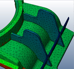
Mesh manipulation tools allow the operator to adapt the meshing used in local areas to gain more detail where needed, typically on smaller features
Hot runner support
The last area of enhancement for this release is the addition of support for hot runner design. Vero has already worked in conjunction with leading hot runner manufacturer Mold-Masters on a separate project for hot runner and hot tip analysis. This platform has been extended, providing a unique analysis tool that can connect to external library providers such as Cadenas and allow users to build up the runner and gate configuration and accurately simulate their use.
The main goal is to investigate exactly what happens in the hot runner system (i.e. pressure drops or resistance time etc) without the need to model and simulate the injected part. This tool gives the user a huge amount of feedback highlighting exactly what’s happening and where.
Conclusion
VISI Flow is a natural compliment to the existing tools within the VISI product range – but it shouldn’t just be considered as a tool for existing VISI users. In fact, the system generated a lot of interest at the recent SolidWorks World event in the US. The fact is that design for injection moulding is an incredibly complex process that many outside of the field may dismiss. It’s not simply a case of designing a core and cavity and shooting it with molten polymers. The mould development itself is complex, not only in terms of geometry, but the process of machine tool set-up.
Injection moulding simulation has been around for many years but it hasn’t experienced a huge take off in the industry because it often takes a non-holistic approach, concentrating on the form of the part and not including runners, gates and other factors which have a huge impact on the success of a project. But when combined with first class mould and die design tools, the potential becomes even greater.
In essence, it’s about using digital tools to first design, then simulate, then iterate both the part design and the associated mould stack – the idea being that when you reach that joyous, yet stomach churning, first off tooling moment, it will ensure you have the optimal design, both in terms of the quality of parts and the required production rates. And in today’s global market, that means competitive advantage.
| Product | VISI Flow 17 |
|---|---|
| Company name | Vero Software |
| Price | On application |


